
Guide/Simboli e blocchi
Draw a Ladder Diagram in AutoCAD — Rungs, Branches and Coil-Contact Cross-References
Aggiornato il November 13, 2026
Realizzato con CADXChange Symbols for AutoCAD Pro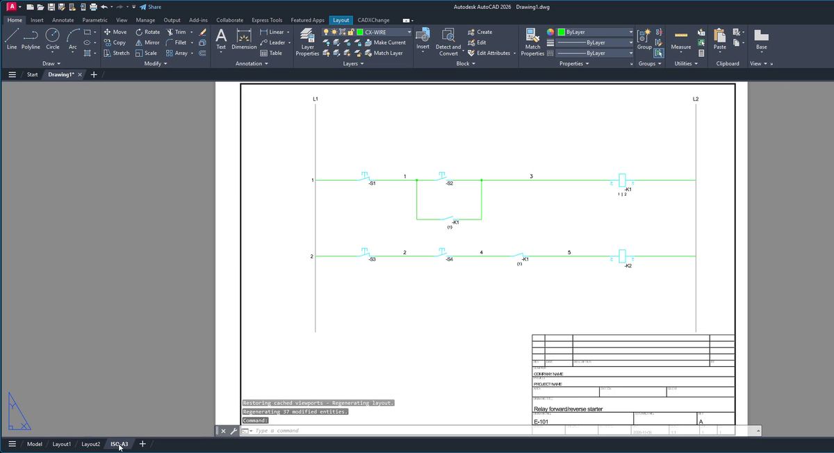
A ladder diagram, with two vertical rails and numbered rungs, is the usual format for relay and contactor control. Drawing the rails and the rungs is easy. The work is in the detail: numbering the rungs, putting each contact under the coil that drives it, and writing next to every coil which rungs its contacts are on, and next to every contact which rung its coil is on. Those cross-references are what let an electrician follow the circuit across the page, and they are the first thing to go out of date when you move a rung.
This guide draws a small relay circuit in plain AutoCAD with the CADXChange palette, including the cross-references. It works on ordinary blocks and ordinary DWG files, with no project files.
1. Set up the drawing and the sheet
Click Set up drawing and type the drawing scale: it creates the standard layers and a text style, and the symbols you place afterwards follow the scale. Then click Sheet, pick the standard and the paper size, and fill in the title and number. A border and a title block are drawn at the drawing scale, a layout is created for printing, and a dashed rectangle in model space shows where to draw.
The picture at the top is the finished result in the layout: the title block says Relay forward/reverse starter, drawing E-101.
2. Draw the ladder
Click Ladder and pick the top left corner, then give the distance between the rails, the number of rungs and the distance between the rungs. The two rails (L1 and L2) and the numbered rungs are drawn, and the command line reports how many rungs were drawn and the number they start from.
3. Place the symbols on the rungs
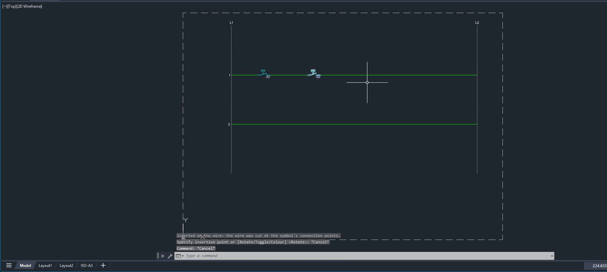
Pick a symbol and click on a rung. With Insert on wires ticked in the palette, the rung is cut at the symbol's leads, so no wire is left running through the symbol, and the command line confirms it. In the picture, pushbuttons -S1 and -S2 are on rung 1 and the cursor is ready for the next symbol.
With Link contacts to coils ticked, a contact takes the tag of the coil that drives it, so you do not type the tag again for every contact.
4. Add the self-holding branch
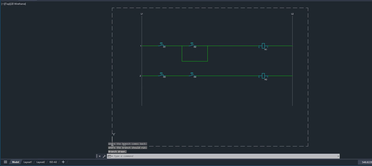
A start button needs a contact in parallel that keeps the coil energised after you let go. Click Branch, then click where the branch leaves the wire, where it comes back, and how far it should run. The branch is drawn as a parallel path around the start button, and the contact goes on it.
5. Write the cross-references
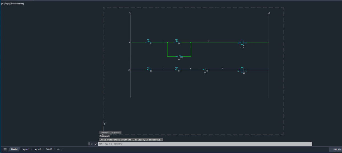
Click Cross-references. The coil gets a line of rung numbers under its tag: the rungs of its make contacts, then a bar, then the rungs of its break contacts. Coil -K1 shows 1 | 2: one make contact on rung 1 and one break contact on rung 2. Each contact gets the rung of its coil in brackets, here (1). The command line reports how many coils and contacts were written, in this drawing 1 coil and 2 contacts.
The symbols have to sit on rungs drawn with the Ladder tool. If there are none, the tool tells you to draw a ladder first. Run Cross-references again after you move or add a rung, and the references follow.
The same few steps draw a reversing starter, a star-delta sequence or a sequence of interlocks; only the symbols and the number of rungs change. The cross-references are the part worth automating, because they are the part that silently goes wrong when the drawing is edited.
Ladder, Branch and Cross-references are Pro tools of the palette. The palette installs free, and during the 14-day trial every tool is open. It works with the full AutoCAD 2021 to 2027 on Windows; AutoCAD LT is not supported.
Try it in your own drawing
The palette installs free and opens every symbol and tool for 14 days, Pro features included. After that the 12 free symbols stay open. Your drawings stay normal DWG files that open anywhere.
See the palette and download the free trial →