
教學/符號與圖塊
P&ID in Plain AutoCAD Without Plant 3D — Equipment Tags, Nozzle Table and Equipment Sheet
更新於 November 13, 2026
使用 CADXChange Symbols for AutoCAD Pro 製作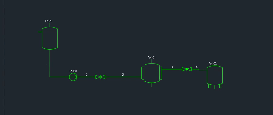
A great many P&IDs are simply drawings: a process flow with vessels, pumps and heat exchangers, lines and tags, handed over as a DWG, with no 3D plant model behind it and no project database to set up.
This guide draws that kind of P&ID in plain AutoCAD with the CADXChange palette and covers the parts that are tedious by hand: equipment tags, the data on each piece of equipment, checking that every nozzle is connected, renumbering after the layout changes, and the equipment list.
1. Place equipment with tags that count up
Pick an equipment symbol and click in the drawing; the size follows the drawing scale and the tag counts up by itself. In the picture, tank T-101, pump P-101 and vessels V-101 and V-102 are placed and joined with pipes. Number wires gave each pipe a running number, 1 to 5, to refer to in notes and lists. That is a simple line number, not a line class system: your own designation scheme (size, service, specification) stays yours.
2. Fill in the equipment data once
Equipment data opens the data of one piece of equipment in a dialog: service, fluid, design pressure and temperature, material, volume, duty, flow and motor power. It is written into the symbol, so it stays with the equipment and is ready for lists and tables. Resize sets the width and height of a vessel, tank or column: the symbol is stretched to the size you type and the text keeps its height.
3. Check the nozzles before anyone else does
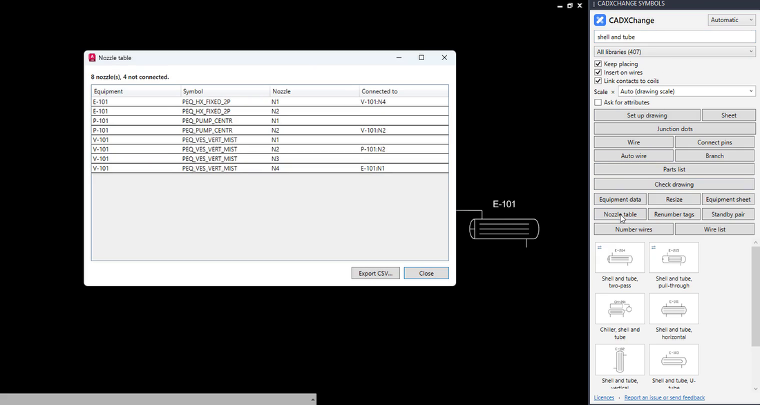
Click Nozzle table. It lists the nozzles of every piece of equipment (N1, N2, ...) with the nozzle each one is wired to; a nozzle that is not connected shows an empty cell. In the picture the header reads 8 nozzles, 4 not connected, and E-101 N1 is connected to V-101 N4. An open nozzle that should have a pipe, or a pipe that goes nowhere, shows up here at once. Export CSV saves the table for Excel.
4. Renumber the tags when the layout changes
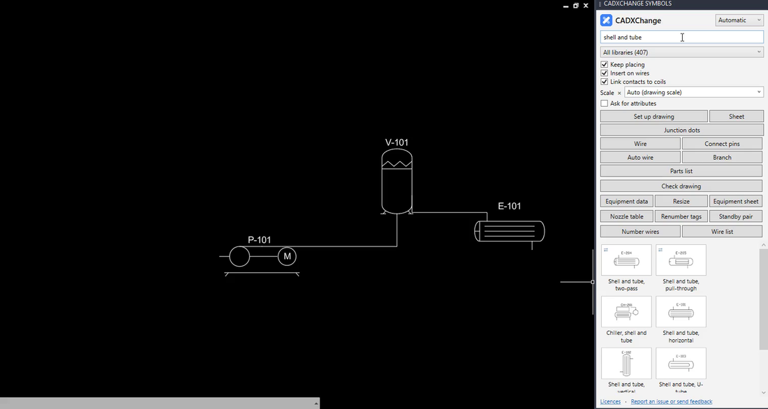
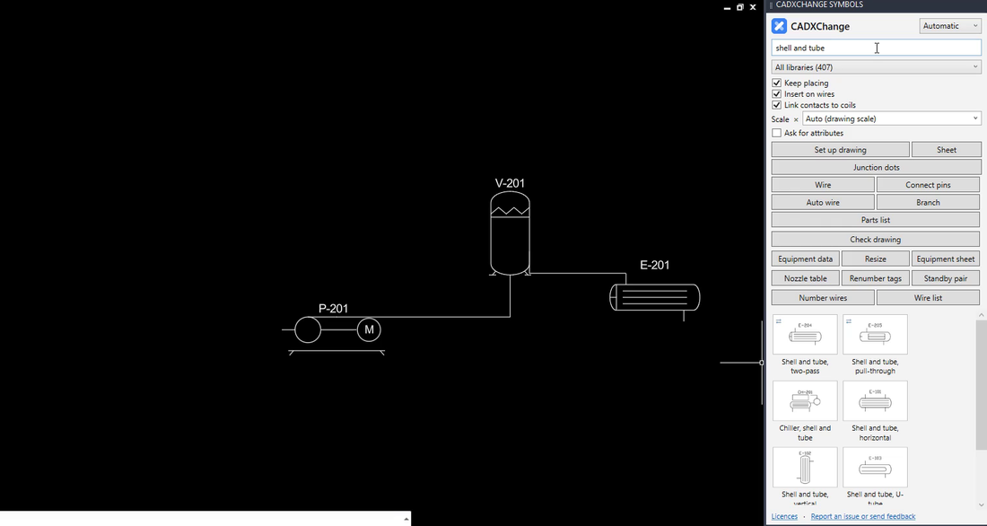
Move equipment around and the tags no longer read in order. Click Renumber tags and type the first number to use: the tags are renumbered by type (P-, V-, E-, ...), left to right and top to bottom. A standby pair such as P-101A and P-101B keeps its letters and moves together. In the pictures a drawing with P-101, V-101 and E-101 becomes P-201, V-201 and E-201.
Standby pair does the other direction of the same job: pick a pump and click where the standby goes, and a copy with its data is added, with the tags P-101A and P-101B.
5. See the result
The same drawing after Renumber tags with 201 as the first number: V-201, E-201 and P-201, each by type and in drawing order.
6. Export the equipment sheet
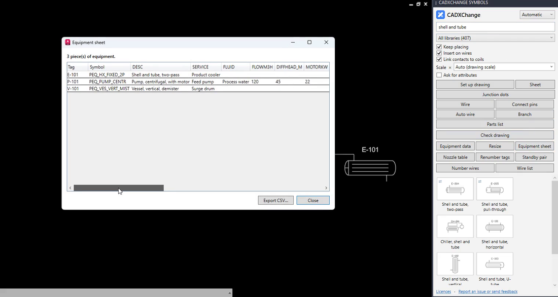
Click Equipment sheet. It lists every tagged piece of equipment with all its data fields, one row each (tag, symbol, description, service, fluid, flow, head, motor power and the rest), and Export CSV opens in Excel as a datasheet. In the picture, three pieces of equipment appear, E-101 as a product cooler, P-101 as a feed pump and V-101 as a surge drum.
None of this makes the drawing a plant model. It keeps a P&ID that is a drawing honest: the tags are in order, the equipment data sits inside the symbols and the lists come from the drawing, not from retyping.
Equipment data, Nozzle table, Renumber tags, Standby pair and Equipment sheet are Pro tools of the process equipment palette. The palette installs free, and during the 14-day trial every tool is open. It works with the full AutoCAD 2021 to 2027 on Windows; AutoCAD LT is not supported.
Try it in your own drawing
The palette installs free and opens every symbol and tool for 14 days, Pro features included. After that the 12 free symbols stay open. Your drawings stay normal DWG files that open anywhere.
See the palette and download the free trial →