

Dwg2Pdf Documentation
Dwg2Pdf has two modes, switched from the top of the window: DWG to PDF — add drawings, pick which layouts go into the PDF and in what order, choose how colors and paper are handled, then plot — and Merge PDF, a standalone tool for combining PDF files you already have. Everything below the mode switch for DWG to PDF (the Layers and Blocks tabs, the Output panel) is described first, followed by the Merge PDF mode.
Getting started
Screenshots reflect a recent release — minor visual details may differ from the version you have installed.
DWG to PDF
Adding files and choosing layouts
Add drawings, then pick which layouts are included and the order they'll appear in the output.
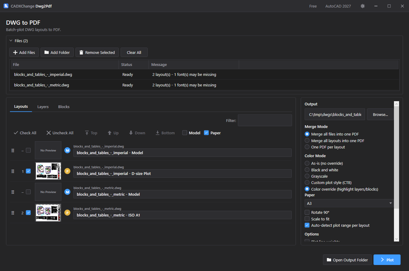
- Add Files picks individual .dwg files; Add Folder scans a whole folder (and its subfolders) for drawings. Either way, every layout in every added file is scanned immediately and listed with a live thumbnail preview.
- Remove Selected drops the highlighted rows from the Files list; Clear All empties it and resets the layout list.
- The layout list below the Files panel is flattened across every added file — you don't have to select one file at a time to see its layouts. Each row shows a thumbnail, the source file name, an editable PDF bookmark title (defaults to "{file} - {layout}"), and a P/M badge marking Paper space vs. Model space.
- Check the box on a row to include that layout in the output; unchecked layouts are skipped entirely. Check All / Uncheck All toggle every layout at once; the Model and Paper checkboxes above the list bulk-toggle only Model-space or only Paper-space layouts.
- The number to the left of each checked row is its plotted position — this is also the number a Custom plot style (CTB) range refers to (see the Merge, Color Mode and CTB section below). Unchecked rows show "–" since they aren't part of the output.
- Reorder the list by dragging a row's ⠿ handle, or by selecting a row and clicking Top / Up / Down / Bottom. List order is output order: it decides page order inside a merged PDF and, together with Merge Mode, which layouts land in the same file.
- Use the Filter box to narrow the list by file or layout name — filtering only hides rows from view, it doesn't change what's checked or their order.
- If a layout has never been opened/regenerated in AutoCAD, its thumbnail can come back empty; the row shows "No preview" instead of leaving a blank box, so it doesn't look like it's still loading.
- When auto plot range detection (see Paper and plot options) finds a title block frame or takes a weaker guess at the plot extents, that's shown as a small colored line under the bookmark title — accent-colored when confident, amber when it's an uncertain guess, hidden when nothing was found.
Layers tab — per-layer color override and hide
Give specific layers a highlight color, or hide them from the plot entirely, by layer name.
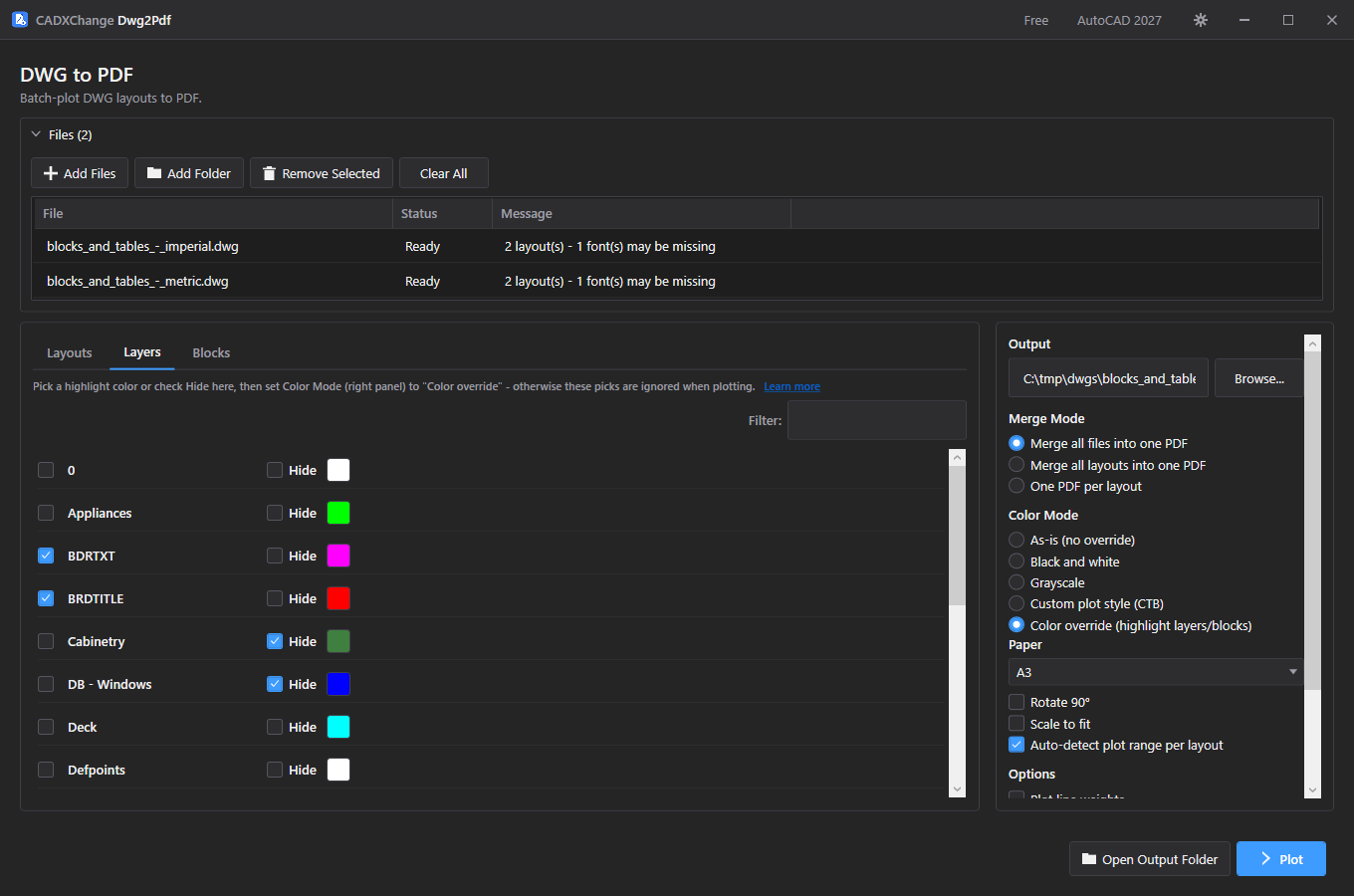
- The Layers tab lists every layer name found across all added files (the union, not per-file) — check a layer's box to mark it Highlighted, and use the color swatch button next to it to pick which color it plots as.
- Check Hide on a layer to drop everything on that layer from the plot completely, instead of (or as well as) recoloring it.
- A pick applies by layer name: every entity on a layer with that name is affected, in every added file — there's no per-file or per-layout override.
- Use the Filter box to find a layer by name when the list is long.
- Important: highlight colors and Hide only take effect on the plot when Color Mode (in the Output panel) is set to Color override. If you pick colors here while a different Color Mode is selected, a warning banner appears at the top of this tab with a one-click "Switch to color override" button — until you switch, these picks are silently ignored when you click Plot.
Blocks tab — per-block color override
Give specific block definitions a highlight color by block name.
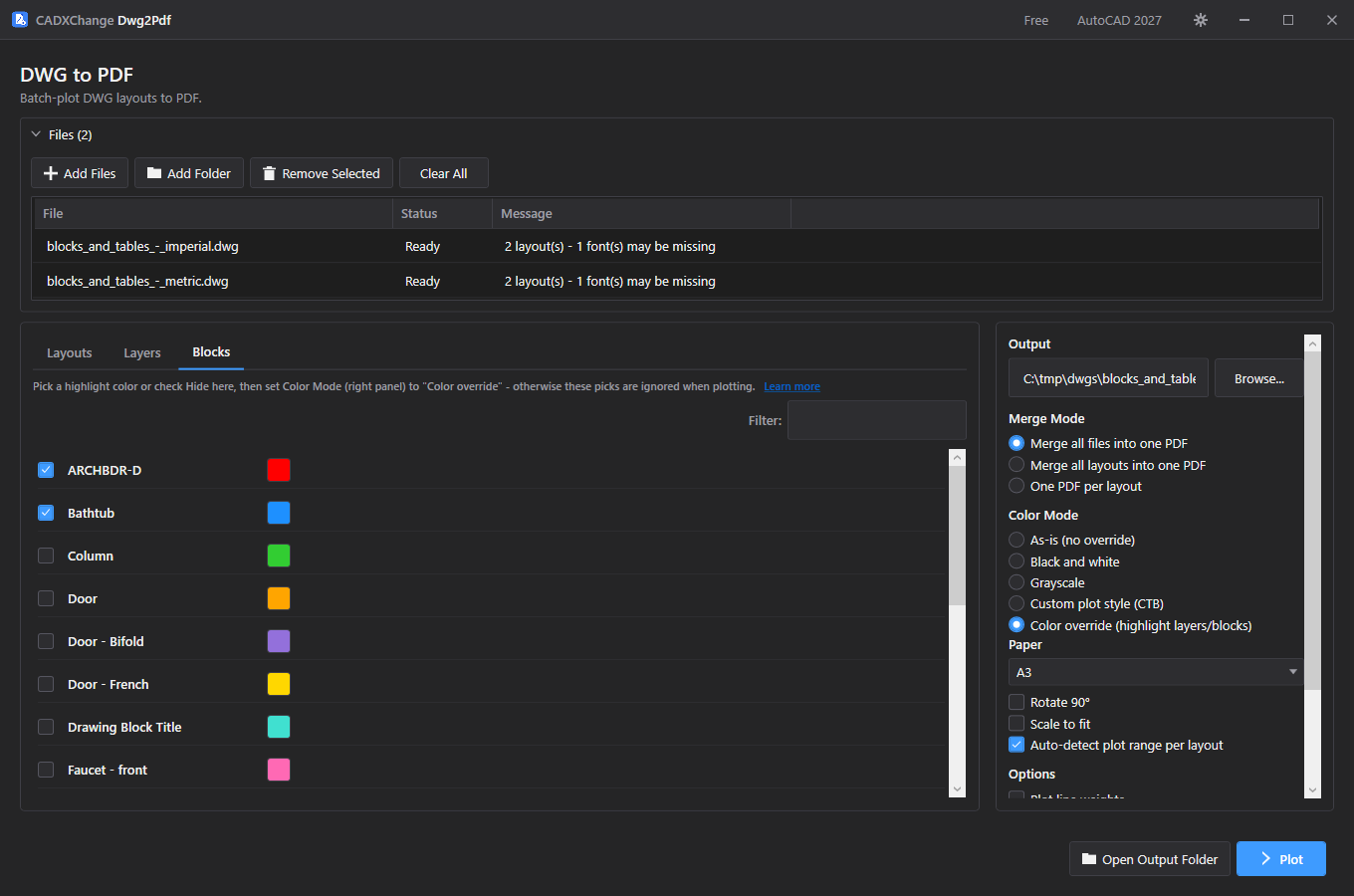
- The Blocks tab lists every block definition name found across all added files. Check a block's box to highlight it, then use the color swatch to pick the plotted color.
- Like layers, a pick applies by block name — every insert of a block with that name is recolored, across every added file. There's no Hide option for blocks (only layers can be hidden).
- Use the Filter box to find a block by name when the list is long.
- Same rule as layers: these colors only take effect when Color Mode is set to Color override. The same warning banner and "Switch to color override" button appear here if a color mode other than Color override is active while you have block colors picked.
Merge Mode, Color Mode and CTB
Control how layouts are grouped into PDF files, and how plotted colors are decided.
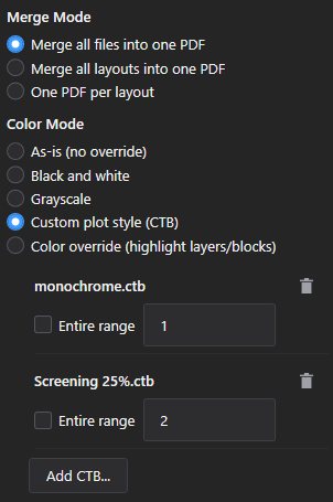
- Merge Mode: "Merge all files into one PDF" combines every checked layout from every file into a single PDF in list order. "Merge all layouts into one PDF" groups by layout name across files instead (all layouts named "A1" together, etc). "One PDF per layout" writes a separate PDF for each checked layout.
- Color Mode — As-is: plot using each entity's own color, exactly as it appears in AutoCAD.
- Color Mode — Black and white: every entity plots pure black on white, regardless of its AutoCAD color.
- Color Mode — Grayscale: colors are converted to their grayscale equivalent brightness rather than flattened to pure black.
- Color Mode — Custom plot style (CTB): applies one or more .ctb plot-style-table files instead of AutoCAD's own colors. Click Add CTB… to attach a file, then either leave it as "Entire range" (applies to every checked layout) or type a specific range using the layout position numbers shown in the layout list, e.g. "1-5,7,13". You can add more than one CTB with different ranges to mix plot styles across a single batch; if two ranges overlap on the same layout, whichever CTB was added later wins.
- Color Mode — Color override: activates the layer/block highlight colors and hidden layers picked on the Layers and Blocks tabs (see those sections above). This is the only Color Mode that reads those tabs' picks — any other Color Mode ignores them.
Paper and plot options
Paper size, orientation, scaling, and the plot-extent switches that affect what's captured on the page.
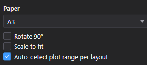
- Paper size offers A4 / A3 / A2 / A1 (and any other sizes exposed by the paper catalog); Rotate 90° swaps the sheet to landscape/portrait; Scale to fit shrinks or grows the drawing to fill the chosen sheet.
- Auto plot range (on by default) uses each layout's own detected plot extents — found from a title block frame where one exists, otherwise a best-effort guess — instead of the paper size chosen here. The paper size above becomes the fallback for any layout where no range could be detected.
- Plot line weights: plots using each entity's assigned lineweight instead of a single uniform weight.
- Scale line weights: scales lineweights proportionally with the plot scale, instead of keeping them at a fixed on-paper thickness.
- Model space: plot extents: for Model-space layouts, plots the drawing's calculated extents (everything drawn). Uncheck it to plot to the drawing's defined limits instead.
Block attribute annotations
Stamp block attribute values onto the PDF as real, selectable/searchable text instead of flat plotted geometry.
- Add block attributes as PDF annotations overlays every block attribute's value as a real PDF text annotation positioned over the plotted geometry, so it can be searched, copied, or read by a screen reader — useful when the underlying attribute text is too small, or styled in a way that plots poorly.
- Paint annotation's interior color (only enabled once the option above is on) fills behind each stamped annotation with a solid color, making it easier to spot which text came from an attribute stamp versus the original plotted drawing.
- The Opacity slider controls how solid that interior fill is, from fully transparent to fully opaque.
Output and plotting
Where PDFs are written, and how a running plot job is monitored or stopped.
- The Output folder field (with Browse…) sets where PDFs are written; Open Output Folder jumps straight to it in File Explorer at any time, including while a plot is still running.
- Plot starts the job; progress is shown as a percentage and an estimated remaining time, with a status message describing the file/layout currently being processed.
- Cancel stops the job after the layout currently in progress finishes — it doesn't abort mid-layout — so any PDFs already written up to that point are kept rather than discarded.
Merge PDF
Merge PDF mode
A separate, standalone tool for combining PDF files that already exist — no DWG or AutoCAD involved.
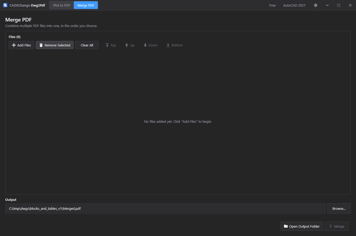
- Switch to Merge PDF from the mode switch at the top of the window. This is a different tool from the Merge Mode option on the DWG to PDF screen: Merge Mode combines PDF pages while plotting DWGs, while Merge PDF combines PDF files that already exist on disk, from any source — scans, other software, or earlier Dwg2Pdf output.
- Add Files opens a picker for one or more .pdf files; files can also be dragged and dropped straight into the list. Duplicate paths are ignored.
- Each row shows the file name; drag its ⠿ handle to reorder it, or select a row and use Top / Up / Down / Bottom. The list order is the page order of the merged output — files aren't split apart, so each file's own pages stay together and in their original order.
- Remove Selected drops the highlighted rows; Clear All empties the whole list.
- The output path defaults to Merged.pdf in the folder the first added file came from, the first time files are added — Browse… picks a different file name or folder. Once you've set an output path yourself (by browsing or typing), it stops auto-updating even if you add more files from a different folder.
- Click Merge to combine every listed file, in list order, into the output path. Each source file also becomes a PDF bookmark (named after the file) in the merged output, so a long merged set can still be navigated file by file. If the output file already exists, Dwg2Pdf appends " (2)", " (3)", etc. rather than overwriting it — the same collision-avoidance behavior as the DWG to PDF plot output.
- Open Output Folder jumps to the merged file's folder once the merge finishes.
Settings
Opened from the gear icon in the title bar. Every field saves immediately — there's no separate Save button.
English / 日本語 / 简体中文. Restart the app for a language change to take effect.
Default: English
System / Light / Dark. Restart the app for a theme change to take effect.
Default: Match system
Which installed AutoCAD version to use first. If it fails to load, the app falls back to another installed version automatically.
Default: Auto (newest installed)
| Setting | Location | Default | What it does |
|---|---|---|---|
| Language | Settings → General | English | English / 日本語 / 简体中文. Restart the app for a language change to take effect. |
| Theme | Settings → General | Match system | System / Light / Dark. Restart the app for a theme change to take effect. |
| AutoCAD version | Settings → AutoCAD | Auto (newest installed) | Which installed AutoCAD version to use first. If it fails to load, the app falls back to another installed version automatically. |
Licensing
Your license status shows in the title bar as Free, Pro, Pro (offline), or Expired, and in full on Settings → License.
To activate: paste your license key into Settings → License → "License key" and click Activate. To move a license to a new machine, click "Deactivate this machine" on the old one first, then activate on the new one.
If the app can't reach the license server (no internet), a previously-activated Pro license keeps working for 14 days as "Pro (offline)". Reconnect within that window to revalidate — past 14 days without a successful check, the license shows as Expired until it can revalidate.
Troubleshooting
"AutoCAD not found" or a plugin trust error when the app starts a job
The app drives AutoCAD in the background to open and process each drawing, so it needs a full, licensed AutoCAD 2021–2027 install — AutoCAD LT is not supported. If AutoCAD is installed but this error still appears, that AutoCAD version has likely never been launched on this machine: open it once (even just to the drawing screen), close it, and try again — AutoCAD only trusts a plugin location after it has run interactively at least once.
A plot run seems to hang on one file
There's no automatic timeout on a plot job — if AutoCAD gets stuck on a file, click Cancel (which kills the whole background process tree for that job) rather than waiting, then check the log folder for what it was doing.
CTB range doesn't apply to the layout I expect
The range numbers refer to each layout's position in the ordered list on screen (the number shown next to each checked row), not to its order in the source DWG — reorder the list first if the numbering looks off.
I picked a layer/block color or checked Hide, but the plot looks unchanged
Layer and block highlight/hide picks only apply when Color Mode is set to Color override. Any other Color Mode (As-is, Black and white, Grayscale, Custom plot style) ignores those picks — the Layers and Blocks tabs show a warning banner with a one-click Switch to color override button when this happens.
Merge PDF fails on one of the files
The error message names the specific file that failed to open — usually a corrupted PDF or one that's password-protected/encrypted. Remove or fix that file and merge again; the other files in the list aren't affected until you retry.
Files on disk
Settings → Diagnostics → Open Log Folder gets you straight to the logs if something needs troubleshooting.
| Settings | %LocalAppData%\CADXChange\Dwg2Pdf\settings.json |
| Logs | %LocalAppData%\CADXChange\Dwg2Pdf\Logs\ |
| Default output folder | Documents\Dwg2Pdf\Output |