
Guides/Drawing standards
How to Set Up a Layout in AutoCAD — Title Block, Scale and Placing Your Drawing in the Sheet
Updated November 11, 2026
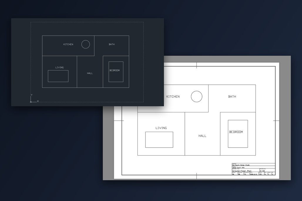
You finished the drawing in the Model tab and now it has to go on a sheet: a frame, a title block, the right scale. That is what a layout is for. The first time, it is also where things go wrong: the drawing is far off to one side, it is tiny, it is cut off, or it looks right until you touch the mouse wheel and the scale changes.
This guide sets up a layout from start to finish, in a way that you can repeat for every sheet. You bring in a sheet with its title block, work out which part of the model one sheet covers at your scale, mark that part from 0,0, and tell the layout to show exactly that. It uses the free title block templates from CADXChange, and it works the same with any sheet whose viewport fills the frame, in AutoCAD and AutoCAD LT.
1. Know the three parts of a layout
A layout is a sheet of paper in AutoCAD. It has three parts that you set up: the sheet itself, which is the frame and the title block; a viewport, which is a window in the sheet that shows your model; and the scale of that viewport, which decides how much of the model fits in the window.
Your drawing stays in the Model tab and is drawn at full size. Nothing is moved or scaled in it when you make a layout. So there are two decisions to make before you start: the paper size, for example A3, and the scale, for example 1:50.
2. Put the sheet and the title block into your drawing
The quickest way to a sheet with a frame and a title block is to take a ready-made one. Download a title block template from CADXChange, choose the paper size and the title block style, and unzip it. Open your own drawing, right-click a layout tab at the bottom (Layout1, for example), choose From Template, pick the DWG you unzipped and select its layout, for example ISO-A3. A new layout tab appears with the frame, the title block and one viewport. Only the paper side comes across, so your model stays as it is. The guide about adding a title block with a free DWG template shows this step by step.
Select the border of the viewport and in the Properties palette set Display locked to No. The template locks the viewport on purpose, so that the mouse wheel cannot change the scale by accident. You unlock it only while you set the view.
3. Work out how much model space one sheet covers
The area is the size of the frame times the scale denominator. On an ISO A3 template the frame is 390 by 277 mm, because the margins are 20 mm on the left and 10 mm on the other three sides. At 1:50 that is 390 × 50 = 19,500 by 277 × 50 = 13,850 millimetres of model space, or 19.5 by 13.85 metres. At 1:100 it is twice that.
For the other ISO sheets the frame is 267 × 190 (A4), 564 × 400 (A2), 811 × 574 (A1) and 1159 × 821 mm (A0). For a US sheet the margins are 0.5 in all round, so ANSI B (17 × 11 in) has a frame of 16 × 10 in; at 1:48, which is 1/4 in = 1 ft, that is 768 × 480 in. Use your drawing units: if you draw in metres, the A3 area at 1:50 is 19.5 by 13.85; if you draw in millimetres, it is 19500 by 13850.
The title block sits in the lower right corner of the frame and is 110 mm wide and 30 mm high, which at 1:50 is 5500 by 1500 model units. Plan the drawing so that nothing important falls in that corner of the area.
4. Mark that area in model space, starting at 0,0
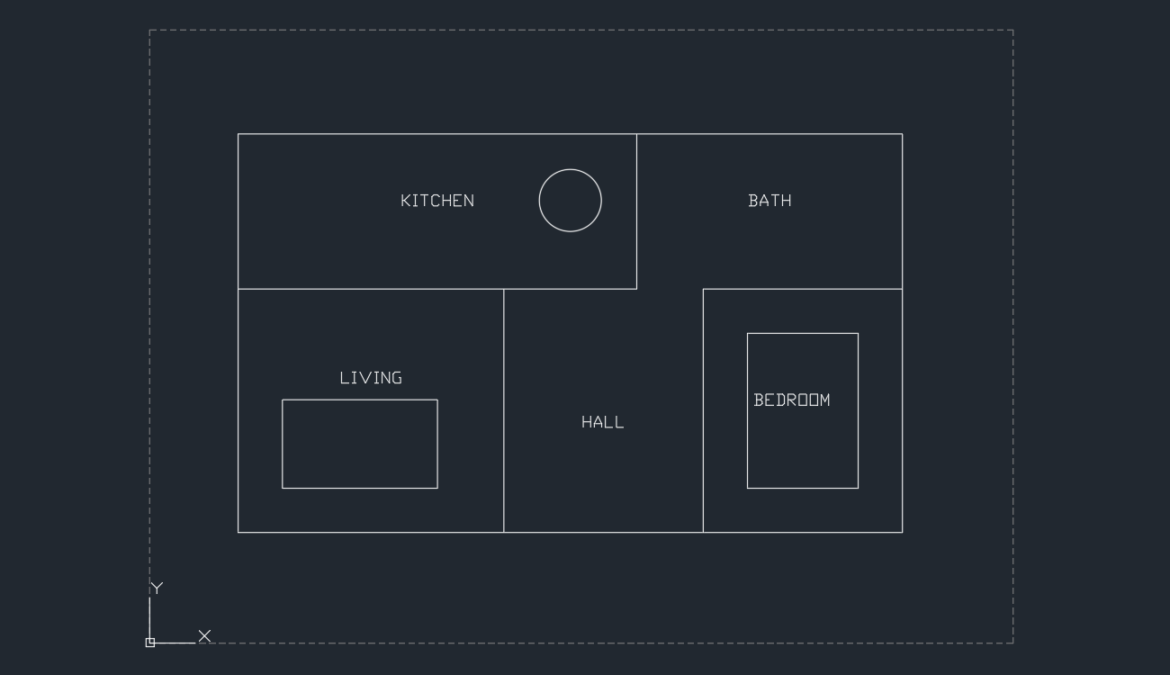
Switch to the Model tab, make a layer for the area (DRAWING-AREA is a good name, with a dashed linetype so it is easy to tell from the drawing) and draw a rectangle with RECTANG: first corner 0,0, other corner 19500,13850. Keep your drawing inside it. With the lower left corner at the origin, the corners of the sheet are always 0,0 and the area size, which you can type without measuring, and every sheet of the project is set up the same way.
If your drawing is already somewhere else in model space, you do not have to move it: start the rectangle at the lower left corner of the part you want on the sheet and use that corner in the next step. The template DWG itself already has such a rectangle in its model space: it is on the layer DRAWING-AREA, starts at 0,0 and is labelled DRAWING AREA (1:1), which is what the viewport shows at 1:1.
5. Set the viewport: show exactly that rectangle at the right scale
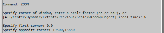
Go back to the layout tab. Double-click inside the viewport to work in it (or type MSPACE). Then run ZOOM, choose the Window option with W, and give the two corners of the rectangle: 0,0 and 19500,13850. Type the coordinates; clicking near the corners is not as exact as typing them. Double-click outside the viewport to return to the sheet.
This works because the rectangle has the same proportions as the viewport. ZOOM Window fits the rectangle to the viewport, so it fills the viewport edge to edge and its centre lands in the centre of the viewport. The scale follows from the same sum as before, which is why you do not have to type it.
6. Check the scale and lock the viewport again
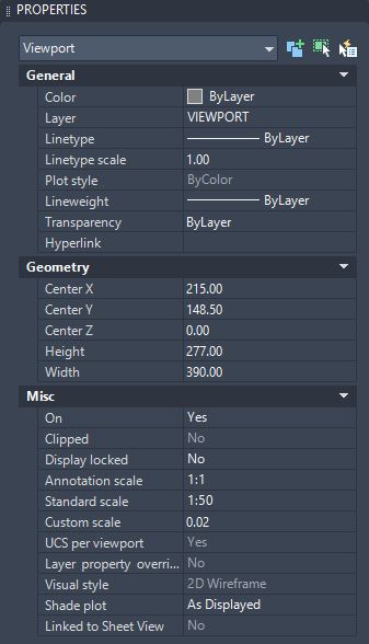
Select the viewport border. In the Properties palette the Standard scale should now read 1:50 and Custom scale 0.02, which is 1/50. If Standard scale shows a custom value that is close but not equal, pick 1:50 from the list so that the viewport carries the exact standard value.
Set Display locked to Yes. From now on, panning or zooming inside the viewport does not change the scale. Zooming with the mouse wheel inside an unlocked viewport does change it, which is how many sheets end up at an odd scale such as 1:49.7.
7. Fill in the title block and keep the area off the print
Double-click the title block and fill in the attributes: company, project, drawing title, number, date and so on. The scale field is plain text, so type 1:50 yourself; it does not read the value from the viewport.
Look at the result. The edges of the area rectangle run along the frame, so you will not see the rectangle inside the sheet, and the drawing sits where you put it in model space. Turn the DRAWING-AREA layer to No Plot, or freeze it, so the dashed lines never reach the paper. The layer stays in the drawing for the next time you adjust the sheet. Then plot with Ctrl+P, or send the layout to PDF.
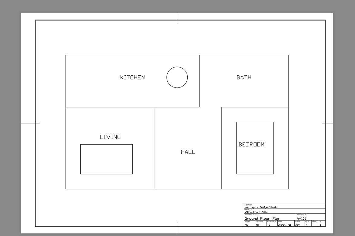
8. Another sheet of the same drawing, or the whole setup in one step
For a second sheet that shows another part of the model, for example the upper floor drawn next to the first, copy the layout (right-click the tab, Move or Copy, tick Create a copy), draw a second area rectangle of the same size around that part and repeat step 5 with the new corners. The scale stays 1:50 because the rectangle has the same size.
If you do this often, the Sheet tool of the CADXChange symbol palette does the same in one go. You choose the paper size and the orientation, it uses the drawing scale you have set in the palette, and you place the lower left corner of the drawing area at the origin (0,0) or pick it in the drawing. It then creates the layout with the frame, the title block and a locked viewport at that scale, and draws the dashed area rectangle in model space. You draw inside the rectangle and the layout is ready to plot.
That is the whole setup: a sheet with a title block, an area worked out from the frame size and the scale, a rectangle from 0,0 that marks it, ZOOM Window with its two corners, and the lock. The scale you read in the Properties palette is then a result of the rectangle, not a guess.
The sheet sizes and margins follow common practice in the spirit of ISO 5457 and ASME Y14.1; check your company or client standard if it asks for different margins, and change the area sum accordingly. The templates are free to use and modify in your own projects.
Before you start — common questions
- How do I set up a layout in AutoCAD?
- Bring in a sheet with a frame and a title block, for example with From Template on the layout tab, then set the viewport: decide the scale, work out the model area one sheet covers (frame size times the scale denominator), draw it as a rectangle in model space, unlock the viewport and use ZOOM Window on that rectangle, then lock the viewport and fill in the title block.
- How do I put a title block in a layout?
- The easiest way is to insert a layout that already contains one: right-click a layout tab, choose From Template and select a DWG with a sheet layout, such as a CADXChange title block template. The title block comes in as a block with attributes, so you double-click it to fill in the project, the title, the number and the date.
- How do I make a layout viewport show a specific area of model space in AutoCAD?
- Draw a rectangle around the area in model space, unlock the viewport, double-click inside it and run ZOOM with the Window option, typing the two opposite corners of that rectangle. If the rectangle has the same proportions as the viewport, it fills the viewport exactly. Then lock the viewport again.
- How big is the model area that an A3 sheet shows at 1:50?
- The area is the size of the viewport times the scale denominator. On an ISO A3 template the viewport is 390 by 277 mm, so at 1:50 the area is 19,500 by 13,850 mm, which is 19.5 by 13.85 metres. At 1:100 it is 39,000 by 27,700 mm.
- How do I set a viewport to an exact scale such as 1:50 in AutoCAD?
- Select the viewport border and choose 1:50 in the Standard scale box of the Properties palette, or in the viewport scale list of the status bar. If you also need the right part of the model in the frame, zoom to a window of the right size first, as in this guide, and then confirm the standard scale.
- Why does my viewport scale change when I use the mouse wheel?
- Zooming inside an unlocked viewport changes its scale. Panning does not. Set Display locked to Yes in the Properties palette when the scale is right, and unlock it only when you want to change the view on purpose.
- My drawing is in metres, not millimetres. What area do I use?
- Convert the sum to your units. A frame of 390 by 277 mm at 1:50 covers 19.5 by 13.85 metres, so you draw the rectangle from 0,0 to 19.5,13.85. If the drawing is in inches and the paper is in millimetres, multiply the frame by the scale and divide by 25.4.
- How do I stop the area rectangle from printing?
- Put it on its own layer and set that layer to No Plot, or freeze it. On the sheet the rectangle runs along the frame, so it is hardly visible, but it is easy to keep it off the print.