
A jacketed batch reactor line with cascade temperature control, in one drawing
Feed tank, pump, filter and flow control, the jacketed reactor with its heat exchanger loop and cascade temperature control, rupture disc and safety valve, vent scrubber and vacuum pump, and the discharge to a centrifuge and dryer: equipment and piping parts from the Pro palette, placed and tagged on one sheet.
Free to use and modify in your own projects, including commercial ones. The ZIP holds the sample drawing, a template, a plot style table and a README; no add-in needed. The data in the drawing is made up, so it is not for design or construction. Provided as is, without warranty. Library terms (CXL-1.0)
Version 1.0 · updated November 14, 2026
Free with a CADXChange account: sign in and the download starts. Up to 3 drawings a day.
This sample uses these resources
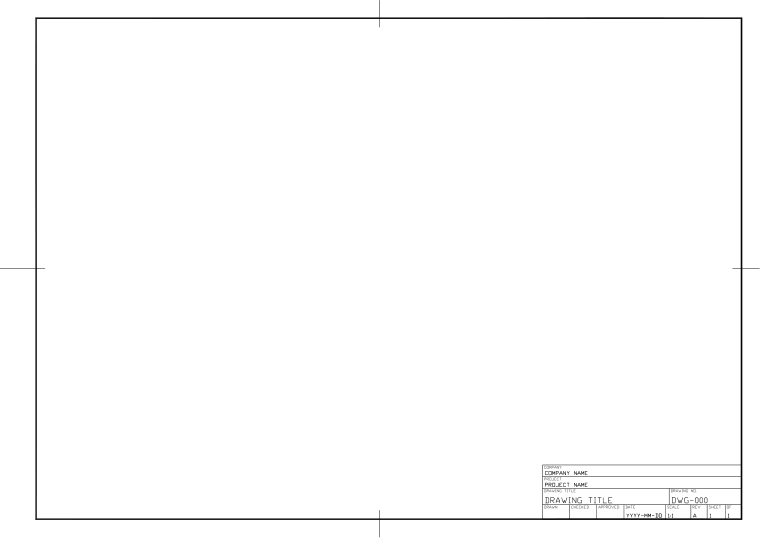
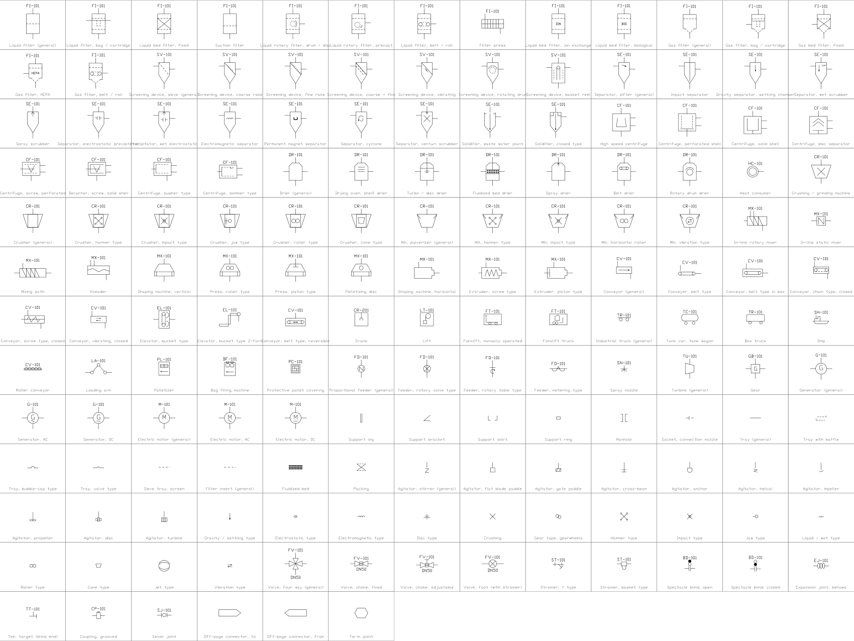
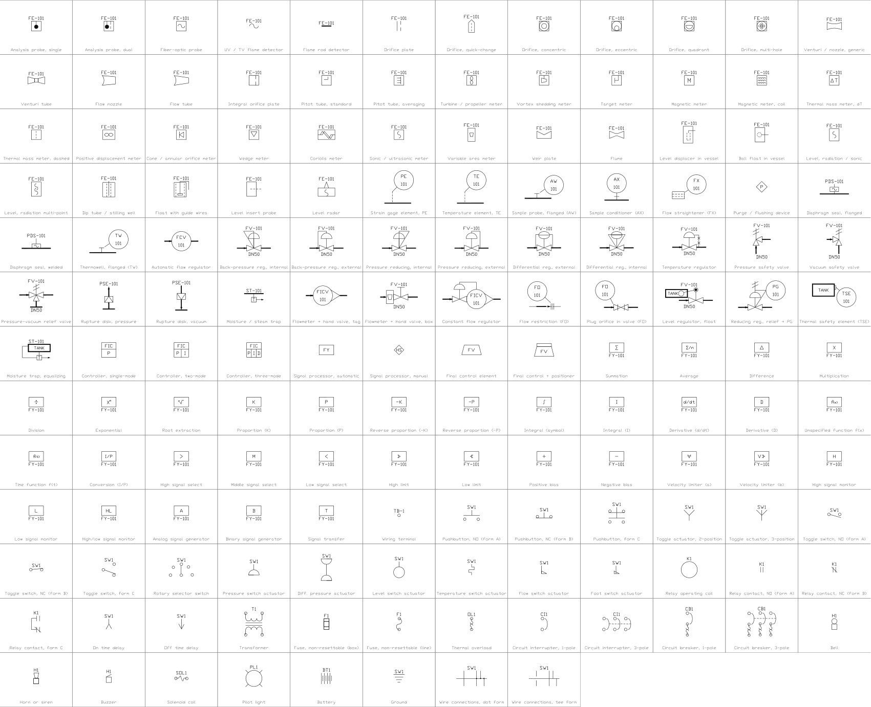
The symbols are blocks from our own libraries, with their attributes filled in. The sheet and its title block come from our ISO A3 title block template. Download them to draw your own diagrams.
What is in the ZIP
- PID-Batch-Reactor-Sample.dwg
Sample drawing (DWG, AutoCAD 2018 format) - Process-Template-ISO-A3.dwt
Template (DWT) that the drawing was made on - CADXChange-Monochrome.ctb
Plot style table (CTB) that prints every colour black - README.txt
README with the layer list and how to use the files
The template
The process template has 14 layers with colours, line weights and linetypes (main, secondary and utility lines, electrical and pneumatic signals, equipment, boundaries, flow arrows, tags, line numbers, text and more), the text styles ISO-2.5 to ISO-5, the dimension style ISO-25 and an ISO A3 layout with a title block and revision table. The layer names are a common convention, not a standard; rename them to match your company's rules.
Layers defined
Every layer in the template with its colour, line weight and linetype, and how many objects of this sample are on it. Layers the sample does not use are still defined, ready for your own drawing.
| Layer | Colour | Line weight | Linetype | Used for | Objects here |
|---|---|---|---|---|---|
| Process layers | |||||
| PROC-PIPE-MAIN | 5 | 0.50 mm | Continuous | Main process lines | 27 |
| PROC-PIPE-SEC | 4 | 0.35 mm | Continuous | Secondary and branch process lines | 6 |
| PROC-PIPE-UTIL | 30 | 0.35 mm | Continuous | Utility lines (steam, condensate, cooling water, air) | 19 |
| PROC-SIGNAL | 3 | 0.18 mm | DASHED | Electrical signal lines | 6 |
| PROC-PNEU | 6 | 0.18 mm | DASHDOT | Pneumatic and capillary signal lines | 7 |
| SYMBOL | 7 | 0.25 mm | Continuous | Symbols (the layer the symbol libraries use) | 28 |
| PROC-EQUIP | 7 | 0.35 mm | Continuous | Equipment outlines drawn outside the symbol libraries | not used here |
| PROC-BOUNDARY | 1 | 0.18 mm | DASHDOT | Package, skid and battery limits | not used here |
| PROC-FLOW | 7 | 0.18 mm | Continuous | Flow arrows and flow direction marks | 13 |
| PROC-TAG | 7 | 0.18 mm | Continuous | Equipment and instrument tags | not used here |
| PROC-LINE-NO | 7 | 0.18 mm | Continuous | Line numbers and line specifications | 13 |
| PROC-TEXT | 7 | 0.18 mm | Continuous | General text | 57 |
| PROC-NOTES | 7 | 0.18 mm | Continuous | Notes and legends | 4 |
| PROC-DIM | 3 | 0.18 mm | Continuous | Dimensions | not used here |
| Sheet and symbol layers | |||||
| 0 | 7 | default | Continuous | Default layer, keep it empty | not used here |
| FRAME | 7 | default | Continuous | Sheet border | 5 |
| TITLEBLOCK | 7 | default | Continuous | Title block and revision table | 1 |
| VIEWPORT | 8 | default | Continuous | Layout viewport frame (does not plot) | 2 |
| DRAWING-AREA | 8 | default | Continuous | Boundary of the model drawing area (does not plot) | 2 |
Styles defined
The text styles, the dimension style and the linetypes that the template defines, so you do not have to set them up in each new drawing.
| Kind | Name | Settings |
|---|---|---|
| Text style | ISO | isocp.shx, 15°, variable height |
| Text style | ISO-2.5 | isocp.shx, 15°, 2.5 mm high |
| Text style | ISO-3.5 | isocp.shx, 15°, 3.5 mm high |
| Text style | ISO-5 | isocp.shx, 15°, 5 mm high |
| Text style | TB-en | Arial, used by the title block |
| Dimension style | ISO-25 | Text 2.5 mm, arrows 2.5 mm, extension lines 1.25 mm beyond the dimension line and 0.625 mm from the object, dimension lines 3.75 mm apart, 0 decimals |
| Linetype | Continuous | Solid line |
| Linetype | DASHED | Dashed |
| Linetype | DASHDOT | Dash-dot |
| Linetype | CENTER | Centre line |
| Linetype | PHANTOM | Phantom line |
| Linetype | HIDDEN | Hidden line |
Sheet and drawing setup
How the sheet is set up, so your own drawings print the same way.
- Sheet
- ISO A3 landscape, 420 × 297 mm.
- Layout
- One layout named ISO-A3, plotted at 1:1 on full-bleed A3 media, so the sheet has no printer margin.
- Border
- 20 mm from the left edge (binding side) and 10 mm from the other edges; the drawing area inside is 390 × 277 mm.
- Model space
- Units are millimetres. The drawing area is shown at 1:1, so 1 mm in the drawing is 1 mm on paper.
- Title block
- 160 × 79 mm at the lower right, with a four-line revision table above the company, project, title and approval fields.
- Text size
- 2.5 mm for labels and notes, 3.5 mm and 5 mm for headings.
- Linetype scale
- 1, so dashes are sized for plotting at 1:1.
- Plot style
- None set. Pick the CTB from the ZIP in the page setup for black-and-white plots.
Title block fields
The attributes of the title block.
| Attribute | Field on the sheet | Value in this sample |
|---|---|---|
| COMPANY | COMPANY | CADXChange |
| PROJECT | PROJECT | Batch Reactor Line |
| AREA | AREA | Reaction and isolation |
| SYSTEM | SYSTEM | Reactor R-201 |
| CLIENT | CLIENT | Sample |
| TITLE | DRAWING TITLE | Piping and instrumentation diagram |
| DRAWING_NO | DRAWING NO. | P-601 |
| CONTRACT_NO | CONTRACT NO. | — |
| REV | REV | A |
| DRAWN | DRAWN | — |
| CHECKED | CHECKED | — |
| APPROVED | APPROVED | — |
| DATE | DATE | 2026-11-15 |
| SCALE | SCALE | NTS |
| SHEET | SHEET | 1 |
| SHEET_OF | OF | 1 |
Revision table: R1 to R4, each with REV, DATE, DESCRIPTION and BY (16 attributes, empty in this sample).
Blocks in the drawing
The equipment list of the drawing: block name, symbol and how many times it is placed.
| Symbol | Block | Placed |
|---|---|---|
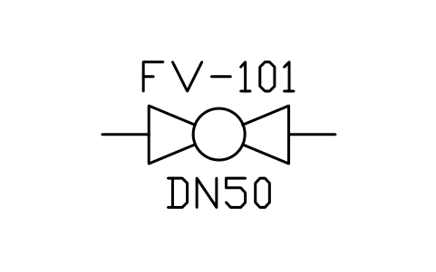 Valve, ball type | PID_VALVE_BALL | 3 |
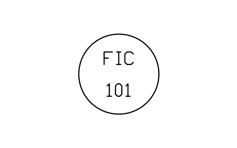 Discrete, field | ISA_DISCRETE_FIELD | 3 |
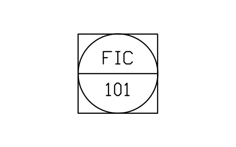 Shared (BPCS), main panel | ISA_SHARED_MAIN | 3 |
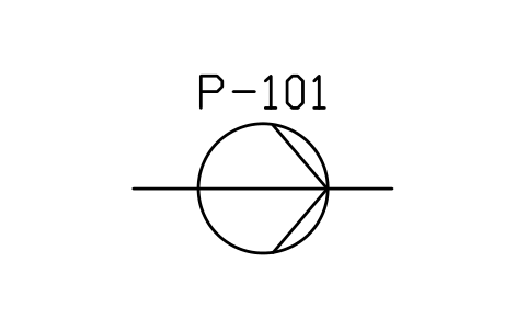 Pump, centrifugal | PID_PUMP_CENTRIFUGAL | 2 |
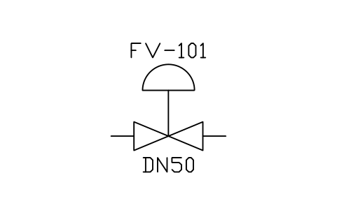 Control valve, diaphragm | ISA_CV_DIAPHRAGM | 2 |
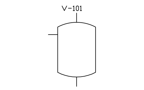 Tank, vessel with dished ends | PID_TANK_DISHED_ENDS | 1 |
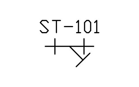 Strainer, Y type | PID_STRAINER_Y | 1 |
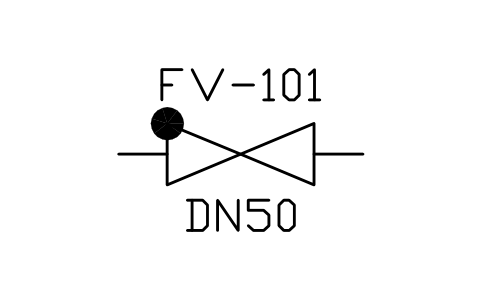 Check valve (general) | PID_CHECK_VALVE | 1 |
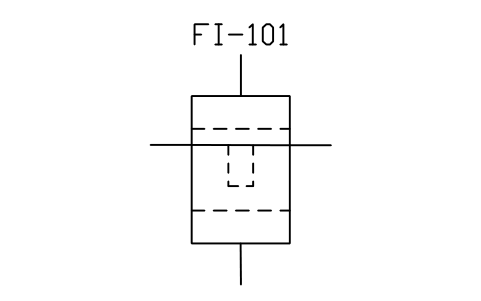 Liquid filter, bag / cartridge | PID_FILTER_CARTRIDGE | 1 |
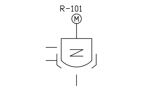 Jacketed vessel with agitator | PID_VESSEL_AGITATED_JACKET | 1 |
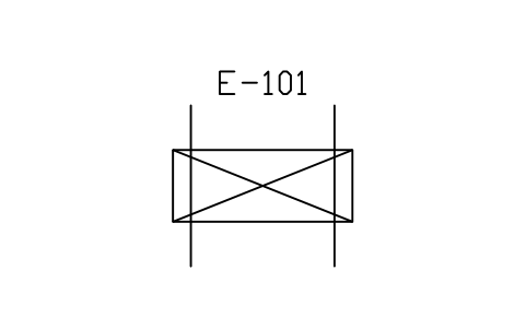 Heat exchanger, plate type | PID_HX_PLATE | 1 |
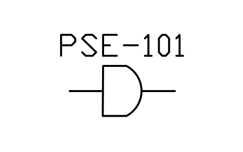 Rupture disc | PID_RUPTURE_DISC | 1 |
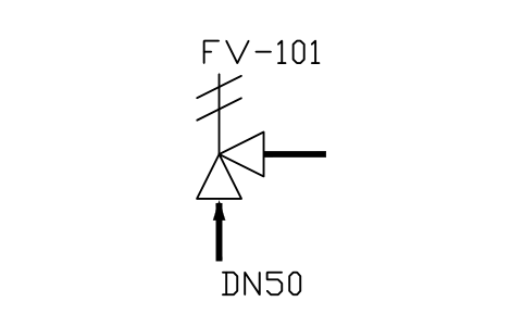 Pressure safety valve | ISA_PSV_PRESSURE | 1 |
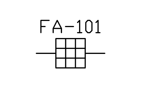 Flame arrestor | PID_FLAME_ARRESTOR | 1 |
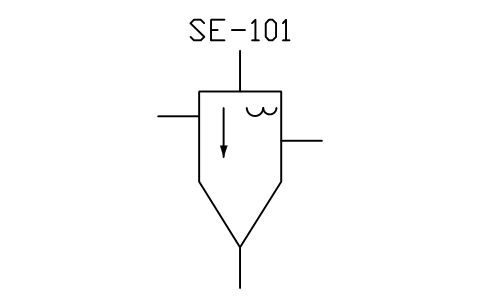 Separator, wet scrubber | PID_SEP_SCRUBBER_WET | 1 |
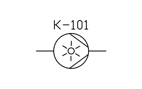 Compressor, liquid ring | PID_COMPRESSOR_LIQUID_RING | 1 |
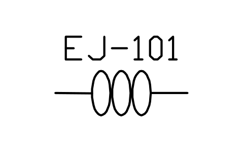 Expansion joint, bellows | PID_BELLOWS | 1 |
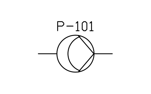 Pump, diaphragm | PID_PUMP_DIAPHRAGM | 1 |
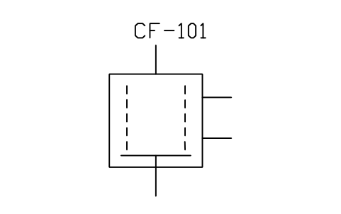 Centrifuge, perforated shell | PID_CENTRIFUGE_PERFORATED | 1 |
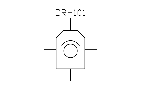 Rotary drum drier | PID_DRIER_ROTARY | 1 |
Equipment schedule
One row per placed symbol, read from the attributes of the blocks in the drawing: what is shown on the sheet, and the schedule attributes that were filled in but are not shown.
| Tag | Description | Shown on the sheet | Filled in, not shown |
|---|---|---|---|
| TK-101 | Tank, vessel with dished endsPID_TANK_DISHED_ENDS | SERVICE = Feed tankCONTENT = Process liquidVOLUME_M3 = 25DESIGN_PRESSURE = 0.5 bar gDESIGN_TEMP = 60 CMATERIAL = SS 304 | |
| S-101 | Strainer, Y typePID_STRAINER_Y | ||
| P-101 | Pump, centrifugalPID_PUMP_CENTRIFUGAL | SERVICE = FeedFLUID = Process liquidFLOW_M3H = 60DIFF_HEAD_M = 45POWER_KW = 11DRIVER = Electric motorMATERIAL = SS 316 | |
| FL-101 | Liquid filter, bag / cartridgePID_FILTER_CARTRIDGE | ||
| R-201 | Jacketed vessel with agitatorPID_VESSEL_AGITATED_JACKET | ||
| E-201 | Heat exchanger, plate typePID_HX_PLATE | ||
| P-201 | Pump, centrifugalPID_PUMP_CENTRIFUGAL | SERVICE = FeedFLUID = Process liquidFLOW_M3H = 60DIFF_HEAD_M = 45POWER_KW = 11DRIVER = Electric motorMATERIAL = SS 316 | |
| RD-201 | Rupture discPID_RUPTURE_DISC | ||
| FA-301 | Flame arrestorPID_FLAME_ARRESTOR | ||
| SC-301 | Separator, wet scrubberPID_SEP_SCRUBBER_WET | ||
| VP-301 | Compressor, liquid ringPID_COMPRESSOR_LIQUID_RING | ||
| EJ-201 | Expansion joint, bellowsPID_BELLOWS | ||
| P-202 | Pump, diaphragmPID_PUMP_DIAPHRAGM | ||
| CF-401 | Centrifuge, perforated shellPID_CENTRIFUGE_PERFORATED | ||
| DR-401 | Rotary drum drierPID_DRIER_ROTARY |
Manufacturer, model and remarks are left empty on every block, ready for your data. The values are examples.
How to use it
- Open the sample drawing to see how layers, text and the title block are used, or open it in the browser first, nothing to install.
- Start your own drawing from the template (NEW, then pick the DWT file). Copy the CTB file to your plot styles folder if you want black-and-white plots.
- Insert blocks from the symbol library into your drawing. The blocks in the sample are copies; they do not change when a library changes.
Frequently asked questions
- Can I use the drawing for a real project?
- As a starting point for layout and layers, yes. The ratings, settings and cable sizes are made up, so the diagram has to be checked and changed for your project before it is used for design or construction.
- Why are the layers coloured?
- Colours and line weights follow the layers: power circuits are red and heavy, control is cyan, signal is green. The plot style table in the ZIP prints everything black and keeps the line weights, so you can plot in black and white as well.
- Which CAD programs open it?
- The drawing and the template are in AutoCAD 2018 format, which AutoCAD 2018 and later open, and so do other CAD programs that read this format. The browser viewer needs nothing installed.