ResourcesSingle-line diagram symbolsPower supply single-line diagrams
Rooftop solar, 52.8 kWp
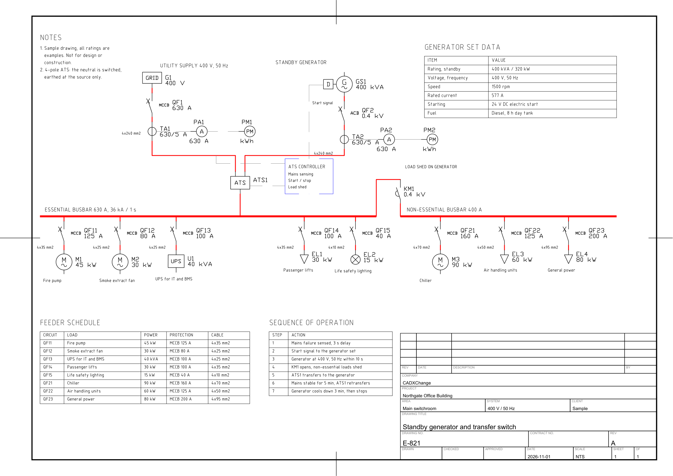
Six strings, DC busbar, isolator and surge protection, inverter, interface protection, metering and the 400 V main board.
Free to use and modify in your own projects, including commercial ones. The ZIP holds the sample drawing, a template, a plot style table and a README; no add-in needed. The data in the drawing is made up, so it is not for design or construction. Provided as is, without warranty. Library terms (CXL-1.0)
This sample uses these resources
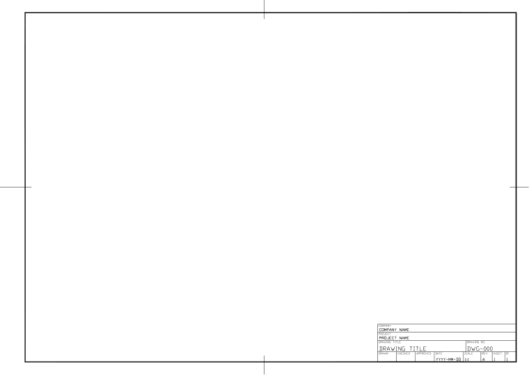
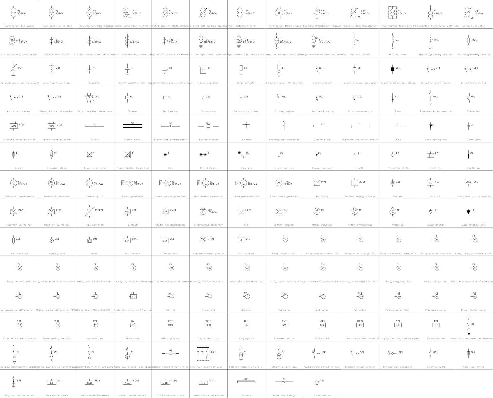
The symbols are blocks from our own libraries, with their attributes filled in. The sheet and its title block come from our ISO A3 title block template. Download them to draw your own diagrams.
Layers, styles and sheet setup are the same for every drawing in the series; they are described on the series page: Power supply single-line diagrams
Title block fields
The attributes of the title block.
| Attribute | Field on the sheet | Value in this sample |
|---|---|---|
| COMPANY | COMPANY | CADXChange |
| PROJECT | PROJECT | Northgate Office Building |
| AREA | AREA | Roof and main switchroom |
| SYSTEM | SYSTEM | 400 V / 50 Hz |
| CLIENT | CLIENT | Sample |
| TITLE | DRAWING TITLE | Rooftop photovoltaic system, single line |
| DRAWING_NO | DRAWING NO. | E-831 |
| CONTRACT_NO | CONTRACT NO. | — |
| REV | REV | A |
| DRAWN | DRAWN | — |
| CHECKED | CHECKED | — |
| APPROVED | APPROVED | — |
| DATE | DATE | 2026-11-01 |
| SCALE | SCALE | NTS |
| SHEET | SHEET | 1 |
| OF | OF | 1 |
Revision table: R1 to R4, each with REV, DATE, DESCRIPTION and BY (16 attributes, empty in this sample).
Blocks in the drawing
The equipment list of the drawing: block name, symbol and how many times it is placed.
| Symbol | Block | Placed |
|---|---|---|
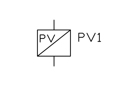 PV array | PWR_GEN_PV | 6 |
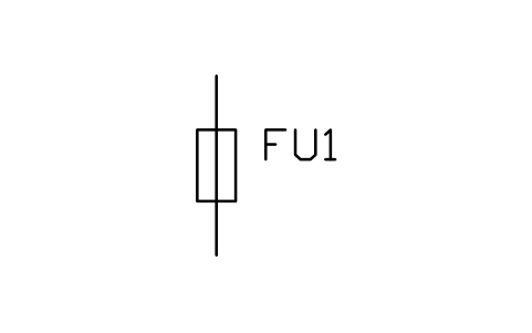 Fuse, low voltage | PWR_LV_FUSE | 6 |
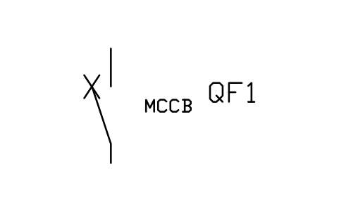 Moulded case circuit breaker | PWR_LV_MCCB | 6 |
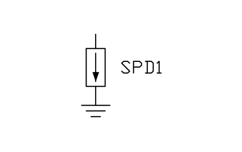 Surge protective device | PWR_LV_SPD | 2 |
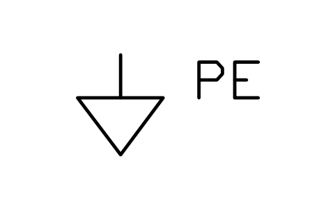 Protective earth | PWR_EARTH_PE | 2 |
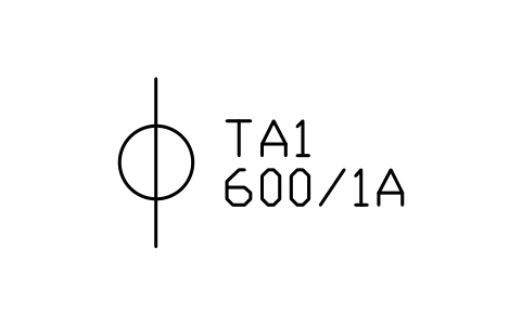 Current transformer | PWR_CT | 2 |
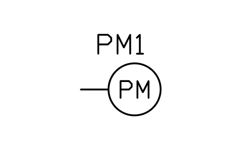 Power meter, multifunction | PWR_M_PM | 2 |
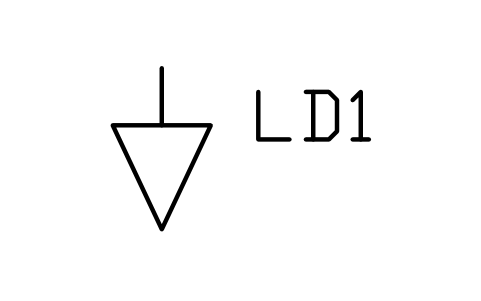 Load (static) | PWR_LOAD | 2 |
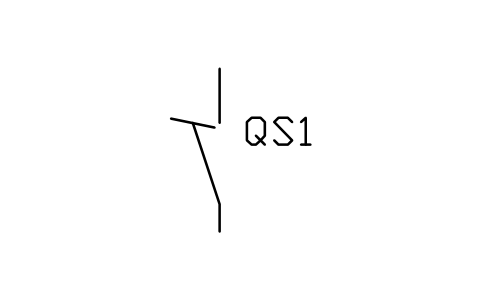 Isolating switch | PWR_LV_ISOLATOR | 1 |
 Inverter (DC to AC) | PWR_INVERTER | 1 |
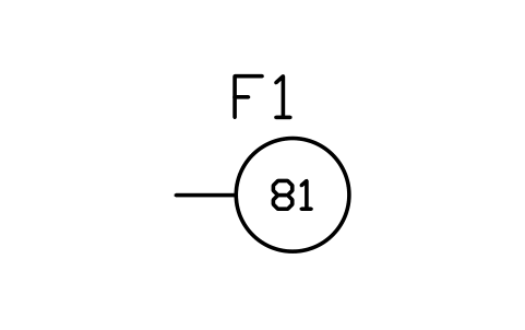 Relay, frequency (81) | PWR_R_81 | 1 |
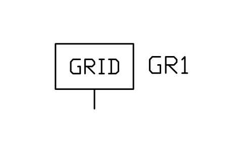 Grid infeed (utility source) | PWR_GRID | 1 |
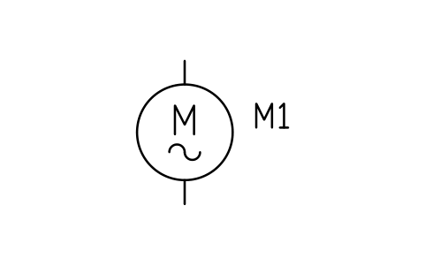 Motor, induction | PWR_MOTOR_IM | 1 |
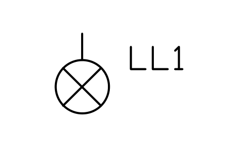 Lighting load | PWR_LOAD_LIGHT | 1 |
Equipment schedule
One row per placed symbol, read from the attributes of the blocks in the drawing: what is shown on the sheet, and the schedule attributes that were filled in but are not shown.
| Tag | Description | Shown on the sheet | Filled in, not shown |
|---|---|---|---|
| PV1 | PV arrayPWR_GEN_PV | VOLTAGE_KV = 0.82UNITS = 20 modules in series | |
| F1 | Fuse, low voltagePWR_LV_FUSE | RATED_CURRENT_A = 20 A | VOLTAGE = 1000 V DCBREAKING_KA = 30TRIP_UNIT = gPVPOLES = 1 |
| PV2 | PV arrayPWR_GEN_PV | VOLTAGE_KV = 0.82UNITS = 20 modules in series | |
| F2 | Fuse, low voltagePWR_LV_FUSE | RATED_CURRENT_A = 20 A | VOLTAGE = 1000 V DCBREAKING_KA = 30TRIP_UNIT = gPVPOLES = 1 |
| PV3 | PV arrayPWR_GEN_PV | VOLTAGE_KV = 0.82UNITS = 20 modules in series | |
| F3 | Fuse, low voltagePWR_LV_FUSE | RATED_CURRENT_A = 20 A | VOLTAGE = 1000 V DCBREAKING_KA = 30TRIP_UNIT = gPVPOLES = 1 |
| PV4 | PV arrayPWR_GEN_PV | VOLTAGE_KV = 0.82UNITS = 20 modules in series | |
| F4 | Fuse, low voltagePWR_LV_FUSE | RATED_CURRENT_A = 20 A | VOLTAGE = 1000 V DCBREAKING_KA = 30TRIP_UNIT = gPVPOLES = 1 |
| PV5 | PV arrayPWR_GEN_PV | VOLTAGE_KV = 0.82UNITS = 20 modules in series | |
| F5 | Fuse, low voltagePWR_LV_FUSE | RATED_CURRENT_A = 20 A | VOLTAGE = 1000 V DCBREAKING_KA = 30TRIP_UNIT = gPVPOLES = 1 |
| PV6 | PV arrayPWR_GEN_PV | VOLTAGE_KV = 0.82UNITS = 20 modules in series | |
| F6 | Fuse, low voltagePWR_LV_FUSE | RATED_CURRENT_A = 20 A | VOLTAGE = 1000 V DCBREAKING_KA = 30TRIP_UNIT = gPVPOLES = 1 |
| F7 | Surge protective devicePWR_LV_SPD | RATED_CURRENT_A = Type 2 | VOLTAGE = 400 VBREAKING_KA = 25TRIP_UNIT = Type 1+2POLES = 3+N |
| PE1 | Protective earthPWR_EARTH_PE | EARTH_TYPE = Protective earth | RESISTANCE_OHM = 10 |
| QS1 | Isolating switchPWR_LV_ISOLATOR | RATED_CURRENT_A = 125 A | VOLTAGE = 1000 V DCTRIP_UNIT = Load breakPOLES = 2 |
| U1 | Inverter (DC to AC)PWR_INVERTER | RATING = 50 kW | VOLTAGE_KV = 0.4UNITS = 1 |
| QF1 | Moulded case circuit breakerPWR_LV_MCCB | RATED_CURRENT_A = 100 A | VOLTAGE = 400 VBREAKING_KA = 25TRIP_UNIT = Thermal-magneticPOLES = 3 |
| TA1 | Current transformerPWR_CT | RATIO = 100/5 A | CLASS = 0.5BURDEN_VA = 10CORES = 1RATED_KV = 0.72 |
| PM1 | Power meter, multifunctionPWR_M_PM | ACCURACY_CLASS = 0.5INPUT = 5 A / 400 VOUTPUT = Modbus RTU | |
| KA1 | Relay, frequency (81)PWR_R_81 | FUNCTION = 27 / 59 / 81 | SETTING = 47.5 to 51.5 HzTRIPS = QF1 |
| G1 | Grid infeed (utility source)PWR_GRID | RATING = 400 V | VOLTAGE_KV = 10 |
| QF2 | Moulded case circuit breakerPWR_LV_MCCB | RATED_CURRENT_A = 160 A | VOLTAGE = 400 VBREAKING_KA = 25TRIP_UNIT = Thermal-magneticPOLES = 3 |
| TA2 | Current transformerPWR_CT | RATIO = 160/5 A | CLASS = 0.5BURDEN_VA = 10CORES = 1RATED_KV = 0.72 |
| PM2 | Power meter, multifunctionPWR_M_PM | ACCURACY_CLASS = 0.5INPUT = 5 A / 400 VOUTPUT = Modbus RTU | |
| F8 | Surge protective devicePWR_LV_SPD | RATED_CURRENT_A = Type 2 | VOLTAGE = 400 VBREAKING_KA = 25TRIP_UNIT = Type 1+2POLES = 3+N |
| PE2 | Protective earthPWR_EARTH_PE | EARTH_TYPE = Protective earth | RESISTANCE_OHM = 10 |
| QF11 | Moulded case circuit breakerPWR_LV_MCCB | RATED_CURRENT_A = 100 A | VOLTAGE = 400 VBREAKING_KA = 36TRIP_UNIT = Thermal-magneticPOLES = 3 |
| M1 | Motor, inductionPWR_MOTOR_IM | POWER_KW = 40 kW | VOLTAGE = 400 VPOWER_FACTOR = 0.85STARTING = Star-deltaSERVICE = Air conditioning |
| QF12 | Moulded case circuit breakerPWR_LV_MCCB | RATED_CURRENT_A = 63 A | VOLTAGE = 400 VBREAKING_KA = 36TRIP_UNIT = Thermal-magneticPOLES = 3 |
| EL1 | Lighting loadPWR_LOAD_LIGHT | POWER_KW = 20 kW | VOLTAGE = 400 VPOWER_FACTOR = 0.95SERVICE = Lighting |
| QF13 | Moulded case circuit breakerPWR_LV_MCCB | RATED_CURRENT_A = 125 A | VOLTAGE = 400 VBREAKING_KA = 36TRIP_UNIT = Thermal-magneticPOLES = 3 |
| EL2 | Load (static)PWR_LOAD | POWER_KW = 60 kW | VOLTAGE = 400 VPOWER_FACTOR = 0.95SERVICE = Small power and IT |
| QF14 | Moulded case circuit breakerPWR_LV_MCCB | RATED_CURRENT_A = 100 A | VOLTAGE = 400 VBREAKING_KA = 36TRIP_UNIT = Thermal-magneticPOLES = 3 |
| EL3 | Load (static)PWR_LOAD | POWER_KW = 44 kW | VOLTAGE = 400 VPOWER_FACTOR = 0.95SERVICE = EV chargers |
Manufacturer, model and remarks are left empty on every block, ready for your data. The values are examples.