
Free ASME B16.5 pipe flanges for AutoCAD (DWG): weld neck, slip-on and blind
ASME B16.5 pipe flanges: 179 ready-made AutoCAD blocks (DWG), free to download and use in your own projects, as a ZIP or one symbol at a time.
179 flange blocks at real size in inches: weld neck, slip-on and blind flanges with a raised face, Class 150, 300 and 600, from NPS 1/2 to 24. Every block shows the side view with the hub and the bore as hidden lines and, next to it, the face view with the raised face, the bolt circle and the bolt holes. Designation, class, facing, material and bore are attributes, so a flange list can be counted straight from the drawings.
Version 1.0 · updated October 17, 2026
Using AutoCAD 2017 or an earlier version? Download the 2010 format
Copyright CADXChange. Use and modify the symbols freely in your own drawings and projects, including commercial ones; credit and a link are needed only when you publish them. Please do not redistribute or resell the library. Each ZIP holds one plain DWG file in AutoCAD 2018 format and a README; no add-in needed. Provided as is, without warranty. Library terms (CXL-1.0)
Related symbol libraries


All 179 symbols
179 of 179 symbols
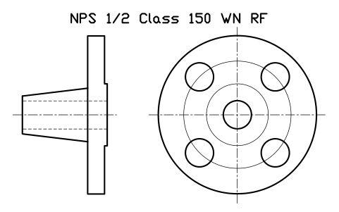
NPS 1/2 Class 150 WN RF
FLG_B165_WN_150_0.5Attributes
DESIGNATIONSTANDARDFLANGE_TYPEPRESSURE_CLASSFACEMATERIALSCHEDULEQTYPART_NOMANUFACTURERREMARKSDESC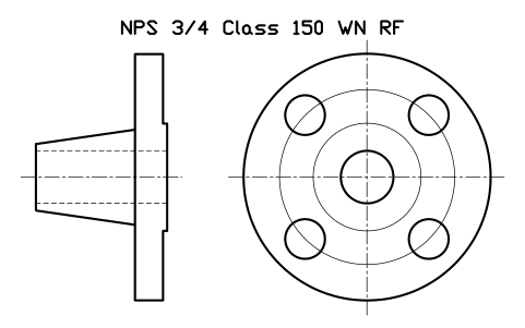
NPS 3/4 Class 150 WN RF
FLG_B165_WN_150_0.75Attributes
DESIGNATIONSTANDARDFLANGE_TYPEPRESSURE_CLASSFACEMATERIALSCHEDULEQTYPART_NOMANUFACTURERREMARKSDESC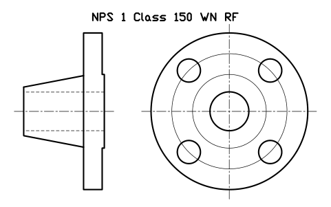
NPS 1 Class 150 WN RF
FLG_B165_WN_150_1Attributes
DESIGNATIONSTANDARDFLANGE_TYPEPRESSURE_CLASSFACEMATERIALSCHEDULEQTYPART_NOMANUFACTURERREMARKSDESC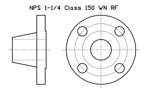
NPS 1-1/4 Class 150 WN RF
FLG_B165_WN_150_1.25Attributes
DESIGNATIONSTANDARDFLANGE_TYPEPRESSURE_CLASSFACEMATERIALSCHEDULEQTYPART_NOMANUFACTURERREMARKSDESC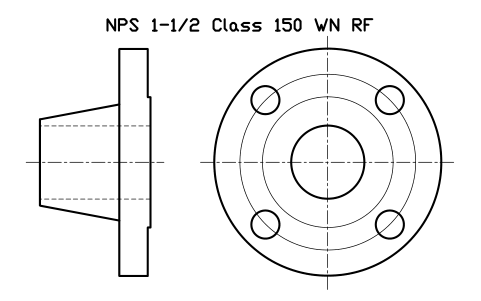
NPS 1-1/2 Class 150 WN RF
FLG_B165_WN_150_1.5Attributes
DESIGNATIONSTANDARDFLANGE_TYPEPRESSURE_CLASSFACEMATERIALSCHEDULEQTYPART_NOMANUFACTURERREMARKSDESC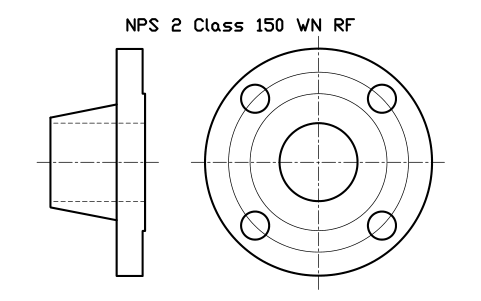
NPS 2 Class 150 WN RF
FLG_B165_WN_150_2Attributes
DESIGNATIONSTANDARDFLANGE_TYPEPRESSURE_CLASSFACEMATERIALSCHEDULEQTYPART_NOMANUFACTURERREMARKSDESC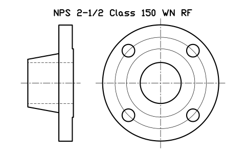
NPS 2-1/2 Class 150 WN RF
FLG_B165_WN_150_2.5Attributes
DESIGNATIONSTANDARDFLANGE_TYPEPRESSURE_CLASSFACEMATERIALSCHEDULEQTYPART_NOMANUFACTURERREMARKSDESC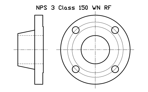
NPS 3 Class 150 WN RF
FLG_B165_WN_150_3Attributes
DESIGNATIONSTANDARDFLANGE_TYPEPRESSURE_CLASSFACEMATERIALSCHEDULEQTYPART_NOMANUFACTURERREMARKSDESC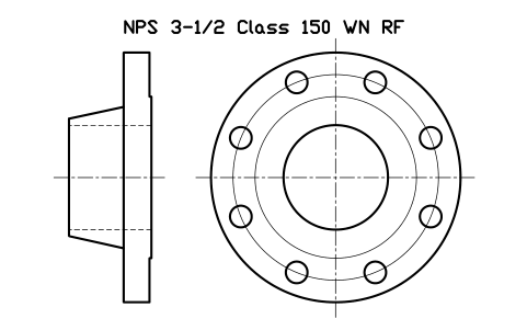
NPS 3-1/2 Class 150 WN RF
FLG_B165_WN_150_3.5Attributes
DESIGNATIONSTANDARDFLANGE_TYPEPRESSURE_CLASSFACEMATERIALSCHEDULEQTYPART_NOMANUFACTURERREMARKSDESC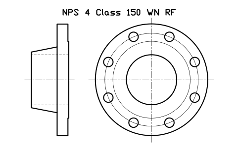
NPS 4 Class 150 WN RF
FLG_B165_WN_150_4Attributes
DESIGNATIONSTANDARDFLANGE_TYPEPRESSURE_CLASSFACEMATERIALSCHEDULEQTYPART_NOMANUFACTURERREMARKSDESC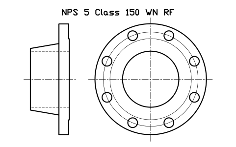
NPS 5 Class 150 WN RF
FLG_B165_WN_150_5Attributes
DESIGNATIONSTANDARDFLANGE_TYPEPRESSURE_CLASSFACEMATERIALSCHEDULEQTYPART_NOMANUFACTURERREMARKSDESC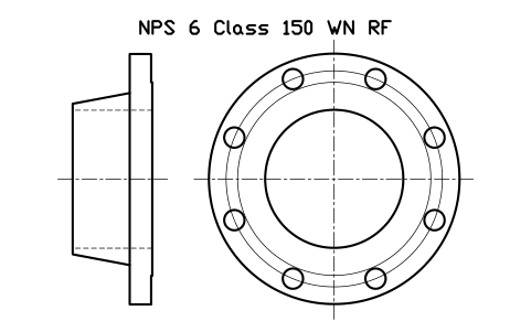
NPS 6 Class 150 WN RF
FLG_B165_WN_150_6Attributes
DESIGNATIONSTANDARDFLANGE_TYPEPRESSURE_CLASSFACEMATERIALSCHEDULEQTYPART_NOMANUFACTURERREMARKSDESC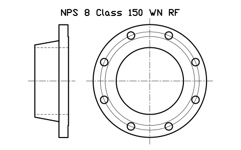
NPS 8 Class 150 WN RF
FLG_B165_WN_150_8Attributes
DESIGNATIONSTANDARDFLANGE_TYPEPRESSURE_CLASSFACEMATERIALSCHEDULEQTYPART_NOMANUFACTURERREMARKSDESC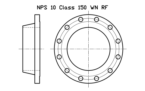
NPS 10 Class 150 WN RF
FLG_B165_WN_150_10Attributes
DESIGNATIONSTANDARDFLANGE_TYPEPRESSURE_CLASSFACEMATERIALSCHEDULEQTYPART_NOMANUFACTURERREMARKSDESC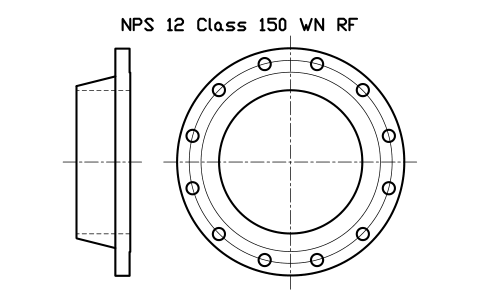
NPS 12 Class 150 WN RF
FLG_B165_WN_150_12Attributes
DESIGNATIONSTANDARDFLANGE_TYPEPRESSURE_CLASSFACEMATERIALSCHEDULEQTYPART_NOMANUFACTURERREMARKSDESC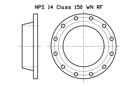
NPS 14 Class 150 WN RF
FLG_B165_WN_150_14Attributes
DESIGNATIONSTANDARDFLANGE_TYPEPRESSURE_CLASSFACEMATERIALSCHEDULEQTYPART_NOMANUFACTURERREMARKSDESC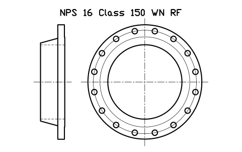
NPS 16 Class 150 WN RF
FLG_B165_WN_150_16Attributes
DESIGNATIONSTANDARDFLANGE_TYPEPRESSURE_CLASSFACEMATERIALSCHEDULEQTYPART_NOMANUFACTURERREMARKSDESC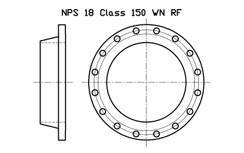
NPS 18 Class 150 WN RF
FLG_B165_WN_150_18Attributes
DESIGNATIONSTANDARDFLANGE_TYPEPRESSURE_CLASSFACEMATERIALSCHEDULEQTYPART_NOMANUFACTURERREMARKSDESC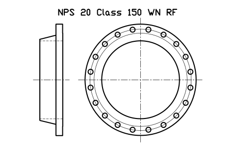
NPS 20 Class 150 WN RF
FLG_B165_WN_150_20Attributes
DESIGNATIONSTANDARDFLANGE_TYPEPRESSURE_CLASSFACEMATERIALSCHEDULEQTYPART_NOMANUFACTURERREMARKSDESC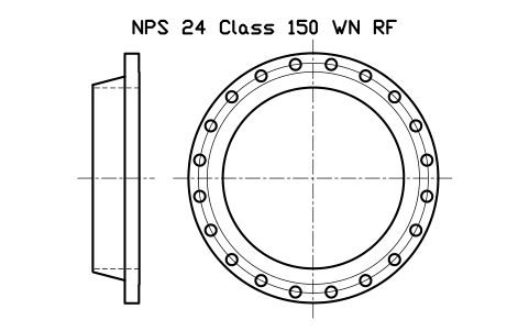
NPS 24 Class 150 WN RF
FLG_B165_WN_150_24Attributes
DESIGNATIONSTANDARDFLANGE_TYPEPRESSURE_CLASSFACEMATERIALSCHEDULEQTYPART_NOMANUFACTURERREMARKSDESC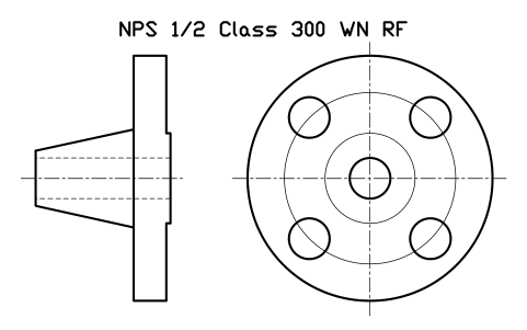
NPS 1/2 Class 300 WN RF
FLG_B165_WN_300_0.5Attributes
DESIGNATIONSTANDARDFLANGE_TYPEPRESSURE_CLASSFACEMATERIALSCHEDULEQTYPART_NOMANUFACTURERREMARKSDESC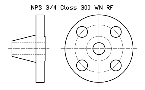
NPS 3/4 Class 300 WN RF
FLG_B165_WN_300_0.75Attributes
DESIGNATIONSTANDARDFLANGE_TYPEPRESSURE_CLASSFACEMATERIALSCHEDULEQTYPART_NOMANUFACTURERREMARKSDESC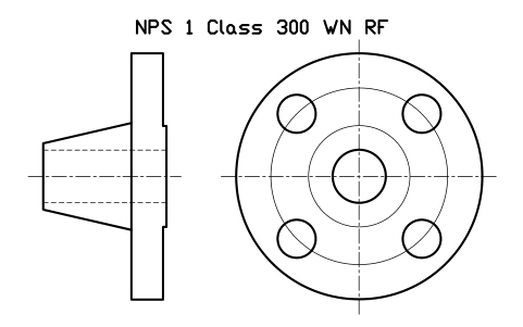
NPS 1 Class 300 WN RF
FLG_B165_WN_300_1Attributes
DESIGNATIONSTANDARDFLANGE_TYPEPRESSURE_CLASSFACEMATERIALSCHEDULEQTYPART_NOMANUFACTURERREMARKSDESC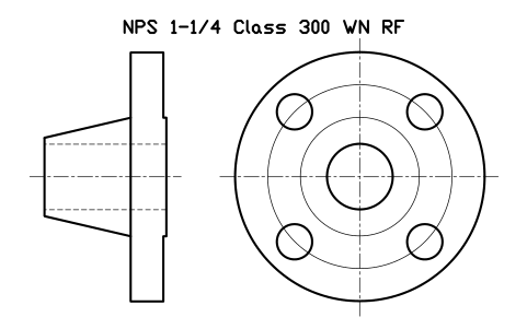
NPS 1-1/4 Class 300 WN RF
FLG_B165_WN_300_1.25Attributes
DESIGNATIONSTANDARDFLANGE_TYPEPRESSURE_CLASSFACEMATERIALSCHEDULEQTYPART_NOMANUFACTURERREMARKSDESC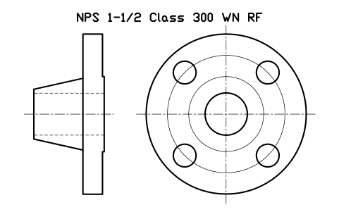
NPS 1-1/2 Class 300 WN RF
FLG_B165_WN_300_1.5Attributes
DESIGNATIONSTANDARDFLANGE_TYPEPRESSURE_CLASSFACEMATERIALSCHEDULEQTYPART_NOMANUFACTURERREMARKSDESC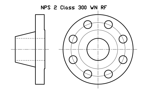
NPS 2 Class 300 WN RF
FLG_B165_WN_300_2Attributes
DESIGNATIONSTANDARDFLANGE_TYPEPRESSURE_CLASSFACEMATERIALSCHEDULEQTYPART_NOMANUFACTURERREMARKSDESC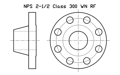
NPS 2-1/2 Class 300 WN RF
FLG_B165_WN_300_2.5Attributes
DESIGNATIONSTANDARDFLANGE_TYPEPRESSURE_CLASSFACEMATERIALSCHEDULEQTYPART_NOMANUFACTURERREMARKSDESC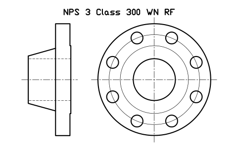
NPS 3 Class 300 WN RF
FLG_B165_WN_300_3Attributes
DESIGNATIONSTANDARDFLANGE_TYPEPRESSURE_CLASSFACEMATERIALSCHEDULEQTYPART_NOMANUFACTURERREMARKSDESC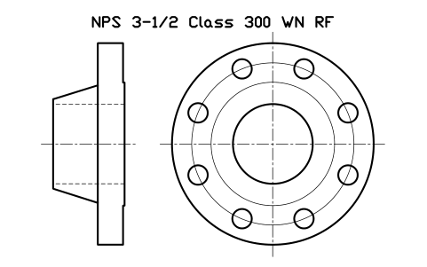
NPS 3-1/2 Class 300 WN RF
FLG_B165_WN_300_3.5Attributes
DESIGNATIONSTANDARDFLANGE_TYPEPRESSURE_CLASSFACEMATERIALSCHEDULEQTYPART_NOMANUFACTURERREMARKSDESC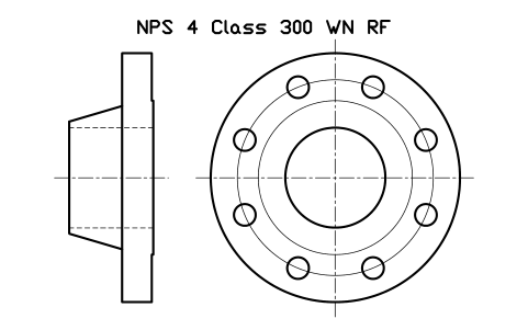
NPS 4 Class 300 WN RF
FLG_B165_WN_300_4Attributes
DESIGNATIONSTANDARDFLANGE_TYPEPRESSURE_CLASSFACEMATERIALSCHEDULEQTYPART_NOMANUFACTURERREMARKSDESC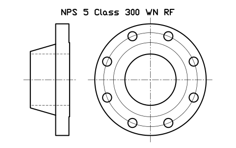
NPS 5 Class 300 WN RF
FLG_B165_WN_300_5Attributes
DESIGNATIONSTANDARDFLANGE_TYPEPRESSURE_CLASSFACEMATERIALSCHEDULEQTYPART_NOMANUFACTURERREMARKSDESC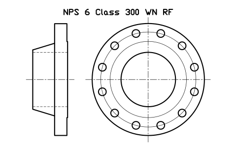
NPS 6 Class 300 WN RF
FLG_B165_WN_300_6Attributes
DESIGNATIONSTANDARDFLANGE_TYPEPRESSURE_CLASSFACEMATERIALSCHEDULEQTYPART_NOMANUFACTURERREMARKSDESC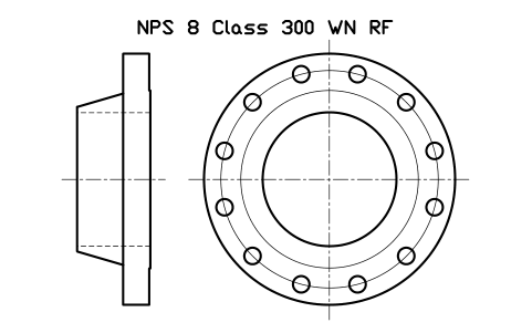
NPS 8 Class 300 WN RF
FLG_B165_WN_300_8Attributes
DESIGNATIONSTANDARDFLANGE_TYPEPRESSURE_CLASSFACEMATERIALSCHEDULEQTYPART_NOMANUFACTURERREMARKSDESC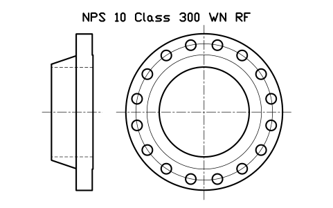
NPS 10 Class 300 WN RF
FLG_B165_WN_300_10Attributes
DESIGNATIONSTANDARDFLANGE_TYPEPRESSURE_CLASSFACEMATERIALSCHEDULEQTYPART_NOMANUFACTURERREMARKSDESC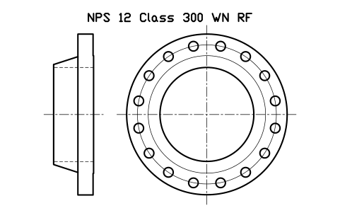
NPS 12 Class 300 WN RF
FLG_B165_WN_300_12Attributes
DESIGNATIONSTANDARDFLANGE_TYPEPRESSURE_CLASSFACEMATERIALSCHEDULEQTYPART_NOMANUFACTURERREMARKSDESC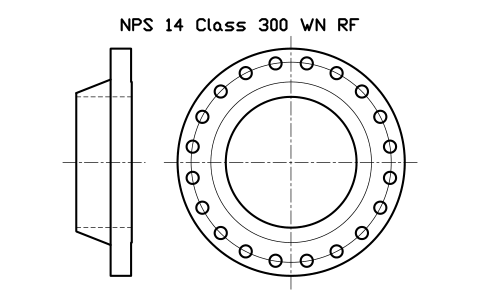
NPS 14 Class 300 WN RF
FLG_B165_WN_300_14Attributes
DESIGNATIONSTANDARDFLANGE_TYPEPRESSURE_CLASSFACEMATERIALSCHEDULEQTYPART_NOMANUFACTURERREMARKSDESC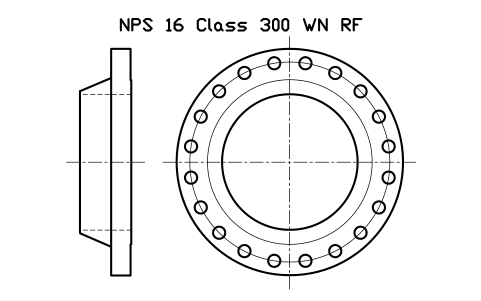
NPS 16 Class 300 WN RF
FLG_B165_WN_300_16Attributes
DESIGNATIONSTANDARDFLANGE_TYPEPRESSURE_CLASSFACEMATERIALSCHEDULEQTYPART_NOMANUFACTURERREMARKSDESC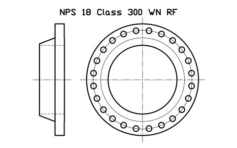
NPS 18 Class 300 WN RF
FLG_B165_WN_300_18Attributes
DESIGNATIONSTANDARDFLANGE_TYPEPRESSURE_CLASSFACEMATERIALSCHEDULEQTYPART_NOMANUFACTURERREMARKSDESC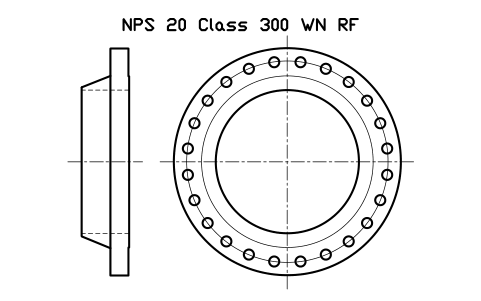
NPS 20 Class 300 WN RF
FLG_B165_WN_300_20Attributes
DESIGNATIONSTANDARDFLANGE_TYPEPRESSURE_CLASSFACEMATERIALSCHEDULEQTYPART_NOMANUFACTURERREMARKSDESC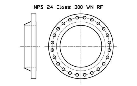
NPS 24 Class 300 WN RF
FLG_B165_WN_300_24Attributes
DESIGNATIONSTANDARDFLANGE_TYPEPRESSURE_CLASSFACEMATERIALSCHEDULEQTYPART_NOMANUFACTURERREMARKSDESC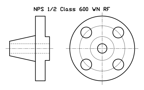
NPS 1/2 Class 600 WN RF
FLG_B165_WN_600_0.5Attributes
DESIGNATIONSTANDARDFLANGE_TYPEPRESSURE_CLASSFACEMATERIALSCHEDULEQTYPART_NOMANUFACTURERREMARKSDESC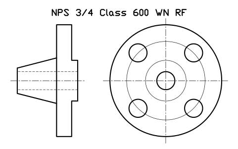
NPS 3/4 Class 600 WN RF
FLG_B165_WN_600_0.75Attributes
DESIGNATIONSTANDARDFLANGE_TYPEPRESSURE_CLASSFACEMATERIALSCHEDULEQTYPART_NOMANUFACTURERREMARKSDESC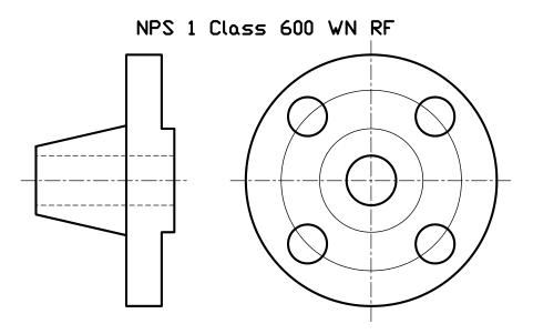
NPS 1 Class 600 WN RF
FLG_B165_WN_600_1Attributes
DESIGNATIONSTANDARDFLANGE_TYPEPRESSURE_CLASSFACEMATERIALSCHEDULEQTYPART_NOMANUFACTURERREMARKSDESC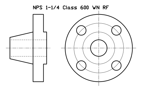
NPS 1-1/4 Class 600 WN RF
FLG_B165_WN_600_1.25Attributes
DESIGNATIONSTANDARDFLANGE_TYPEPRESSURE_CLASSFACEMATERIALSCHEDULEQTYPART_NOMANUFACTURERREMARKSDESC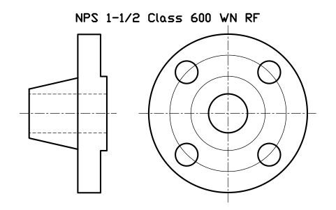
NPS 1-1/2 Class 600 WN RF
FLG_B165_WN_600_1.5Attributes
DESIGNATIONSTANDARDFLANGE_TYPEPRESSURE_CLASSFACEMATERIALSCHEDULEQTYPART_NOMANUFACTURERREMARKSDESC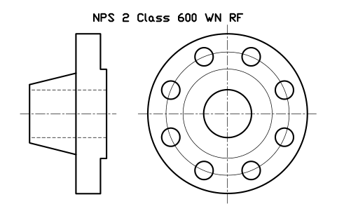
NPS 2 Class 600 WN RF
FLG_B165_WN_600_2Attributes
DESIGNATIONSTANDARDFLANGE_TYPEPRESSURE_CLASSFACEMATERIALSCHEDULEQTYPART_NOMANUFACTURERREMARKSDESC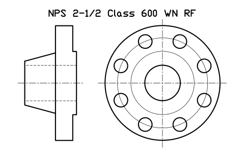
NPS 2-1/2 Class 600 WN RF
FLG_B165_WN_600_2.5Attributes
DESIGNATIONSTANDARDFLANGE_TYPEPRESSURE_CLASSFACEMATERIALSCHEDULEQTYPART_NOMANUFACTURERREMARKSDESC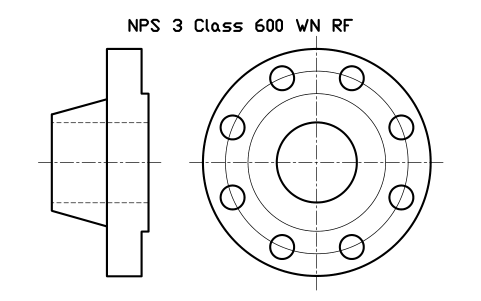
NPS 3 Class 600 WN RF
FLG_B165_WN_600_3Attributes
DESIGNATIONSTANDARDFLANGE_TYPEPRESSURE_CLASSFACEMATERIALSCHEDULEQTYPART_NOMANUFACTURERREMARKSDESC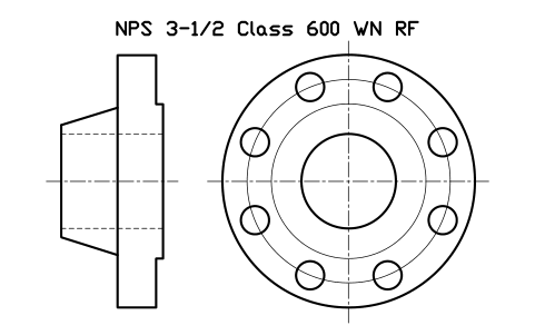
NPS 3-1/2 Class 600 WN RF
FLG_B165_WN_600_3.5Attributes
DESIGNATIONSTANDARDFLANGE_TYPEPRESSURE_CLASSFACEMATERIALSCHEDULEQTYPART_NOMANUFACTURERREMARKSDESC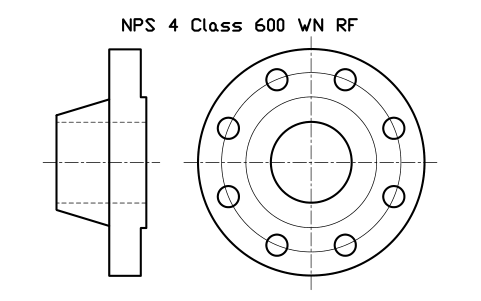
NPS 4 Class 600 WN RF
FLG_B165_WN_600_4Attributes
DESIGNATIONSTANDARDFLANGE_TYPEPRESSURE_CLASSFACEMATERIALSCHEDULEQTYPART_NOMANUFACTURERREMARKSDESC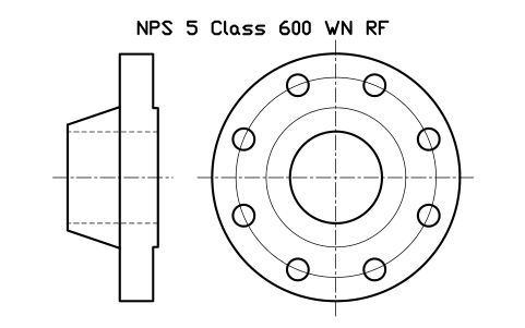
NPS 5 Class 600 WN RF
FLG_B165_WN_600_5Attributes
DESIGNATIONSTANDARDFLANGE_TYPEPRESSURE_CLASSFACEMATERIALSCHEDULEQTYPART_NOMANUFACTURERREMARKSDESC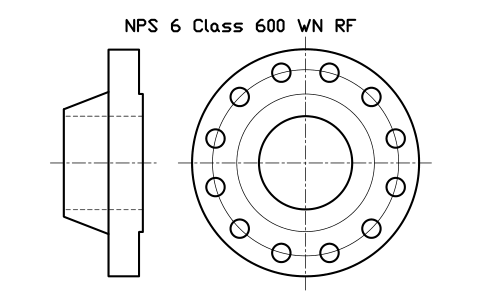
NPS 6 Class 600 WN RF
FLG_B165_WN_600_6Attributes
DESIGNATIONSTANDARDFLANGE_TYPEPRESSURE_CLASSFACEMATERIALSCHEDULEQTYPART_NOMANUFACTURERREMARKSDESC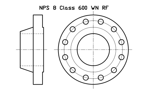
NPS 8 Class 600 WN RF
FLG_B165_WN_600_8Attributes
DESIGNATIONSTANDARDFLANGE_TYPEPRESSURE_CLASSFACEMATERIALSCHEDULEQTYPART_NOMANUFACTURERREMARKSDESC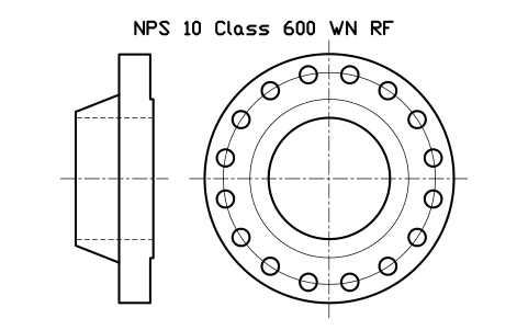
NPS 10 Class 600 WN RF
FLG_B165_WN_600_10Attributes
DESIGNATIONSTANDARDFLANGE_TYPEPRESSURE_CLASSFACEMATERIALSCHEDULEQTYPART_NOMANUFACTURERREMARKSDESC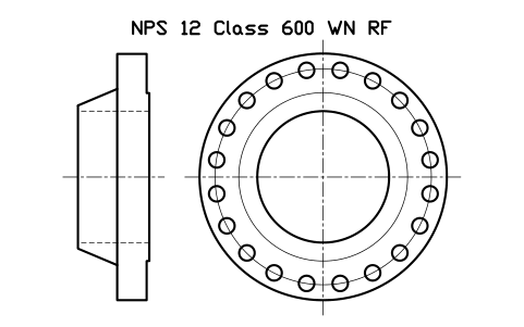
NPS 12 Class 600 WN RF
FLG_B165_WN_600_12Attributes
DESIGNATIONSTANDARDFLANGE_TYPEPRESSURE_CLASSFACEMATERIALSCHEDULEQTYPART_NOMANUFACTURERREMARKSDESC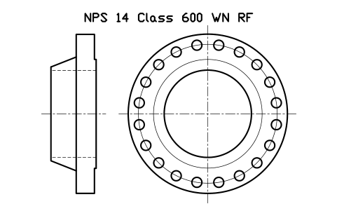
NPS 14 Class 600 WN RF
FLG_B165_WN_600_14Attributes
DESIGNATIONSTANDARDFLANGE_TYPEPRESSURE_CLASSFACEMATERIALSCHEDULEQTYPART_NOMANUFACTURERREMARKSDESC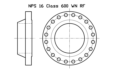
NPS 16 Class 600 WN RF
FLG_B165_WN_600_16Attributes
DESIGNATIONSTANDARDFLANGE_TYPEPRESSURE_CLASSFACEMATERIALSCHEDULEQTYPART_NOMANUFACTURERREMARKSDESC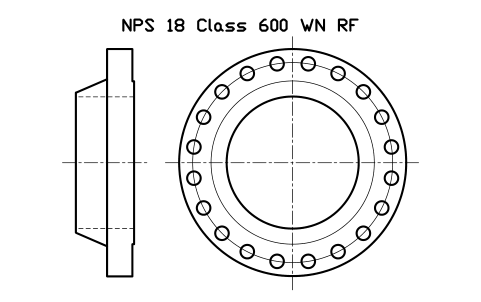
NPS 18 Class 600 WN RF
FLG_B165_WN_600_18Attributes
DESIGNATIONSTANDARDFLANGE_TYPEPRESSURE_CLASSFACEMATERIALSCHEDULEQTYPART_NOMANUFACTURERREMARKSDESC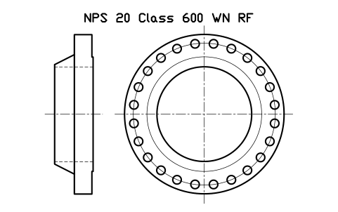
NPS 20 Class 600 WN RF
FLG_B165_WN_600_20Attributes
DESIGNATIONSTANDARDFLANGE_TYPEPRESSURE_CLASSFACEMATERIALSCHEDULEQTYPART_NOMANUFACTURERREMARKSDESC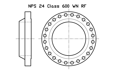
NPS 24 Class 600 WN RF
FLG_B165_WN_600_24Attributes
DESIGNATIONSTANDARDFLANGE_TYPEPRESSURE_CLASSFACEMATERIALSCHEDULEQTYPART_NOMANUFACTURERREMARKSDESC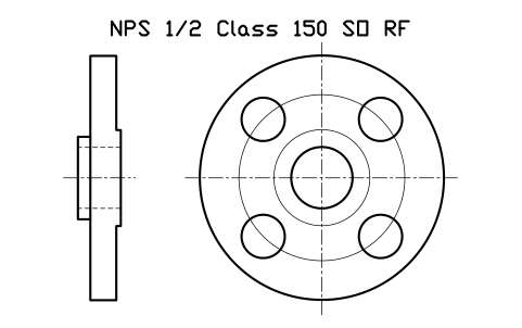
NPS 1/2 Class 150 SO RF
FLG_B165_SO_150_0.5Attributes
DESIGNATIONSTANDARDFLANGE_TYPEPRESSURE_CLASSFACEMATERIALSCHEDULEQTYPART_NOMANUFACTURERREMARKSDESC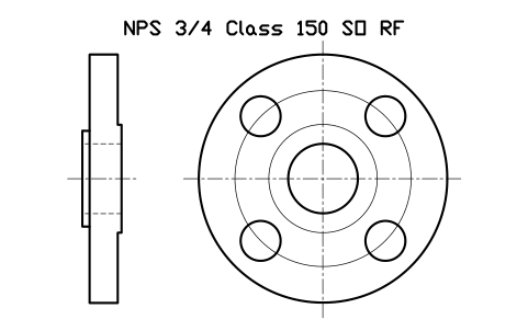
NPS 3/4 Class 150 SO RF
FLG_B165_SO_150_0.75Attributes
DESIGNATIONSTANDARDFLANGE_TYPEPRESSURE_CLASSFACEMATERIALSCHEDULEQTYPART_NOMANUFACTURERREMARKSDESC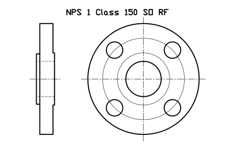
NPS 1 Class 150 SO RF
FLG_B165_SO_150_1Attributes
DESIGNATIONSTANDARDFLANGE_TYPEPRESSURE_CLASSFACEMATERIALSCHEDULEQTYPART_NOMANUFACTURERREMARKSDESC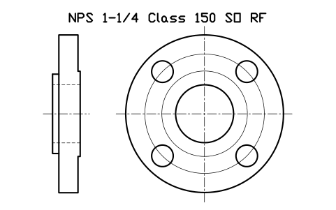
NPS 1-1/4 Class 150 SO RF
FLG_B165_SO_150_1.25Attributes
DESIGNATIONSTANDARDFLANGE_TYPEPRESSURE_CLASSFACEMATERIALSCHEDULEQTYPART_NOMANUFACTURERREMARKSDESC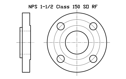
NPS 1-1/2 Class 150 SO RF
FLG_B165_SO_150_1.5Attributes
DESIGNATIONSTANDARDFLANGE_TYPEPRESSURE_CLASSFACEMATERIALSCHEDULEQTYPART_NOMANUFACTURERREMARKSDESC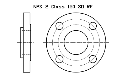
NPS 2 Class 150 SO RF
FLG_B165_SO_150_2Attributes
DESIGNATIONSTANDARDFLANGE_TYPEPRESSURE_CLASSFACEMATERIALSCHEDULEQTYPART_NOMANUFACTURERREMARKSDESC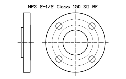
NPS 2-1/2 Class 150 SO RF
FLG_B165_SO_150_2.5Attributes
DESIGNATIONSTANDARDFLANGE_TYPEPRESSURE_CLASSFACEMATERIALSCHEDULEQTYPART_NOMANUFACTURERREMARKSDESC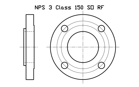
NPS 3 Class 150 SO RF
FLG_B165_SO_150_3Attributes
DESIGNATIONSTANDARDFLANGE_TYPEPRESSURE_CLASSFACEMATERIALSCHEDULEQTYPART_NOMANUFACTURERREMARKSDESC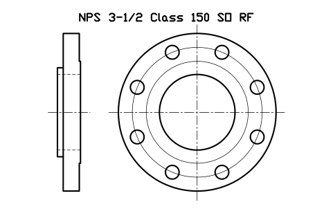
NPS 3-1/2 Class 150 SO RF
FLG_B165_SO_150_3.5Attributes
DESIGNATIONSTANDARDFLANGE_TYPEPRESSURE_CLASSFACEMATERIALSCHEDULEQTYPART_NOMANUFACTURERREMARKSDESC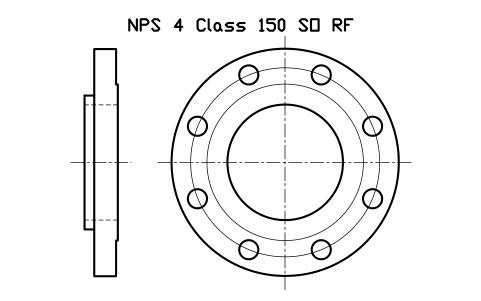
NPS 4 Class 150 SO RF
FLG_B165_SO_150_4Attributes
DESIGNATIONSTANDARDFLANGE_TYPEPRESSURE_CLASSFACEMATERIALSCHEDULEQTYPART_NOMANUFACTURERREMARKSDESC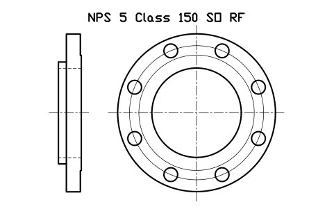
NPS 5 Class 150 SO RF
FLG_B165_SO_150_5Attributes
DESIGNATIONSTANDARDFLANGE_TYPEPRESSURE_CLASSFACEMATERIALSCHEDULEQTYPART_NOMANUFACTURERREMARKSDESC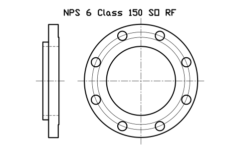
NPS 6 Class 150 SO RF
FLG_B165_SO_150_6Attributes
DESIGNATIONSTANDARDFLANGE_TYPEPRESSURE_CLASSFACEMATERIALSCHEDULEQTYPART_NOMANUFACTURERREMARKSDESC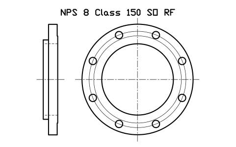
NPS 8 Class 150 SO RF
FLG_B165_SO_150_8Attributes
DESIGNATIONSTANDARDFLANGE_TYPEPRESSURE_CLASSFACEMATERIALSCHEDULEQTYPART_NOMANUFACTURERREMARKSDESC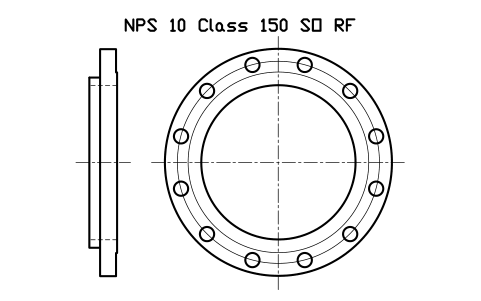
NPS 10 Class 150 SO RF
FLG_B165_SO_150_10Attributes
DESIGNATIONSTANDARDFLANGE_TYPEPRESSURE_CLASSFACEMATERIALSCHEDULEQTYPART_NOMANUFACTURERREMARKSDESC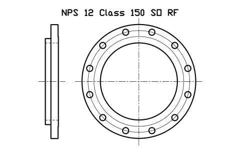
NPS 12 Class 150 SO RF
FLG_B165_SO_150_12Attributes
DESIGNATIONSTANDARDFLANGE_TYPEPRESSURE_CLASSFACEMATERIALSCHEDULEQTYPART_NOMANUFACTURERREMARKSDESC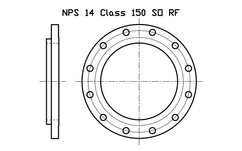
NPS 14 Class 150 SO RF
FLG_B165_SO_150_14Attributes
DESIGNATIONSTANDARDFLANGE_TYPEPRESSURE_CLASSFACEMATERIALSCHEDULEQTYPART_NOMANUFACTURERREMARKSDESC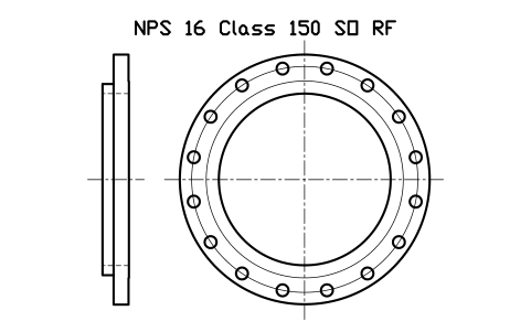
NPS 16 Class 150 SO RF
FLG_B165_SO_150_16Attributes
DESIGNATIONSTANDARDFLANGE_TYPEPRESSURE_CLASSFACEMATERIALSCHEDULEQTYPART_NOMANUFACTURERREMARKSDESC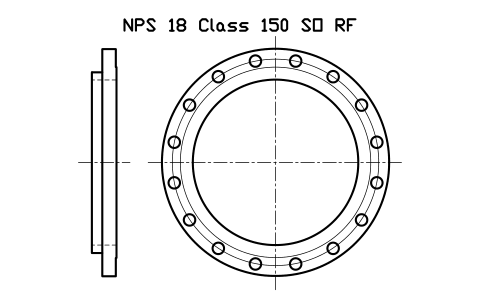
NPS 18 Class 150 SO RF
FLG_B165_SO_150_18Attributes
DESIGNATIONSTANDARDFLANGE_TYPEPRESSURE_CLASSFACEMATERIALSCHEDULEQTYPART_NOMANUFACTURERREMARKSDESC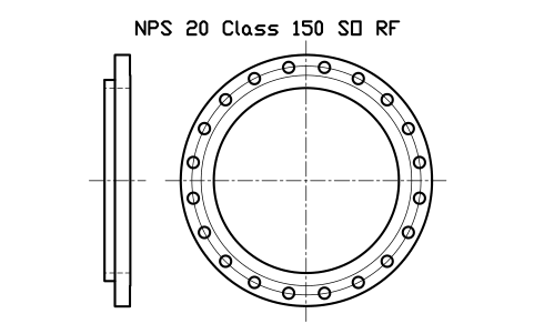
NPS 20 Class 150 SO RF
FLG_B165_SO_150_20Attributes
DESIGNATIONSTANDARDFLANGE_TYPEPRESSURE_CLASSFACEMATERIALSCHEDULEQTYPART_NOMANUFACTURERREMARKSDESC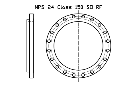
NPS 24 Class 150 SO RF
FLG_B165_SO_150_24Attributes
DESIGNATIONSTANDARDFLANGE_TYPEPRESSURE_CLASSFACEMATERIALSCHEDULEQTYPART_NOMANUFACTURERREMARKSDESC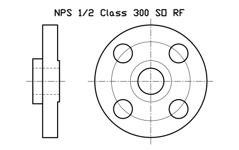
NPS 1/2 Class 300 SO RF
FLG_B165_SO_300_0.5Attributes
DESIGNATIONSTANDARDFLANGE_TYPEPRESSURE_CLASSFACEMATERIALSCHEDULEQTYPART_NOMANUFACTURERREMARKSDESC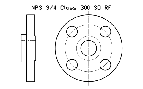
NPS 3/4 Class 300 SO RF
FLG_B165_SO_300_0.75Attributes
DESIGNATIONSTANDARDFLANGE_TYPEPRESSURE_CLASSFACEMATERIALSCHEDULEQTYPART_NOMANUFACTURERREMARKSDESC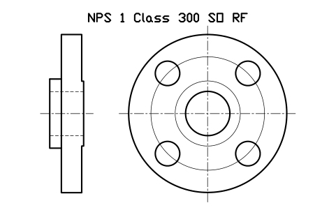
NPS 1 Class 300 SO RF
FLG_B165_SO_300_1Attributes
DESIGNATIONSTANDARDFLANGE_TYPEPRESSURE_CLASSFACEMATERIALSCHEDULEQTYPART_NOMANUFACTURERREMARKSDESC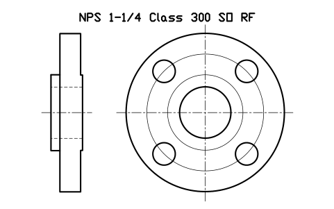
NPS 1-1/4 Class 300 SO RF
FLG_B165_SO_300_1.25Attributes
DESIGNATIONSTANDARDFLANGE_TYPEPRESSURE_CLASSFACEMATERIALSCHEDULEQTYPART_NOMANUFACTURERREMARKSDESC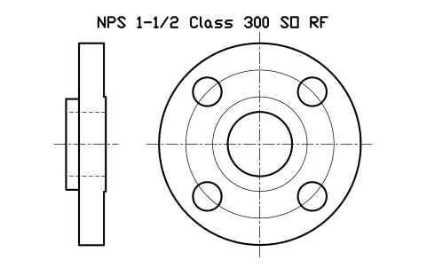
NPS 1-1/2 Class 300 SO RF
FLG_B165_SO_300_1.5Attributes
DESIGNATIONSTANDARDFLANGE_TYPEPRESSURE_CLASSFACEMATERIALSCHEDULEQTYPART_NOMANUFACTURERREMARKSDESC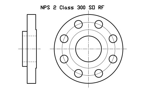
NPS 2 Class 300 SO RF
FLG_B165_SO_300_2Attributes
DESIGNATIONSTANDARDFLANGE_TYPEPRESSURE_CLASSFACEMATERIALSCHEDULEQTYPART_NOMANUFACTURERREMARKSDESC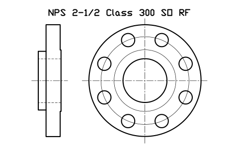
NPS 2-1/2 Class 300 SO RF
FLG_B165_SO_300_2.5Attributes
DESIGNATIONSTANDARDFLANGE_TYPEPRESSURE_CLASSFACEMATERIALSCHEDULEQTYPART_NOMANUFACTURERREMARKSDESC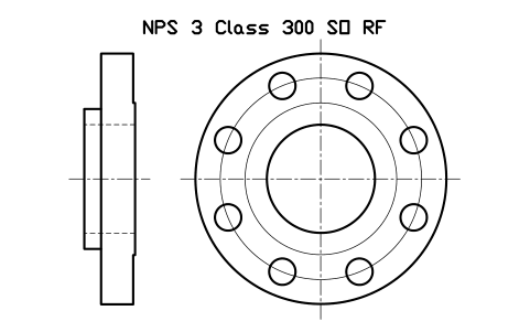
NPS 3 Class 300 SO RF
FLG_B165_SO_300_3Attributes
DESIGNATIONSTANDARDFLANGE_TYPEPRESSURE_CLASSFACEMATERIALSCHEDULEQTYPART_NOMANUFACTURERREMARKSDESC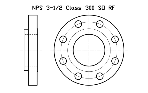
NPS 3-1/2 Class 300 SO RF
FLG_B165_SO_300_3.5Attributes
DESIGNATIONSTANDARDFLANGE_TYPEPRESSURE_CLASSFACEMATERIALSCHEDULEQTYPART_NOMANUFACTURERREMARKSDESC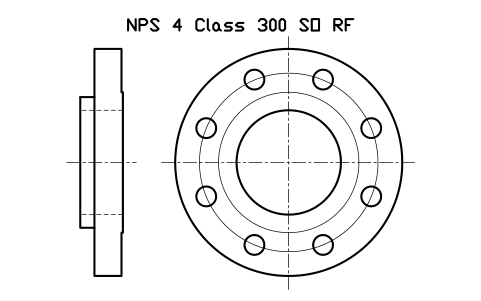
NPS 4 Class 300 SO RF
FLG_B165_SO_300_4Attributes
DESIGNATIONSTANDARDFLANGE_TYPEPRESSURE_CLASSFACEMATERIALSCHEDULEQTYPART_NOMANUFACTURERREMARKSDESC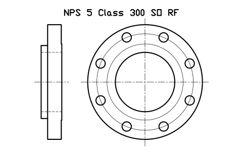
NPS 5 Class 300 SO RF
FLG_B165_SO_300_5Attributes
DESIGNATIONSTANDARDFLANGE_TYPEPRESSURE_CLASSFACEMATERIALSCHEDULEQTYPART_NOMANUFACTURERREMARKSDESC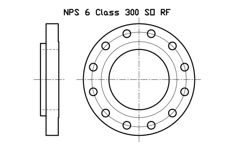
NPS 6 Class 300 SO RF
FLG_B165_SO_300_6Attributes
DESIGNATIONSTANDARDFLANGE_TYPEPRESSURE_CLASSFACEMATERIALSCHEDULEQTYPART_NOMANUFACTURERREMARKSDESC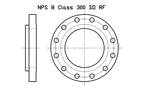
NPS 8 Class 300 SO RF
FLG_B165_SO_300_8Attributes
DESIGNATIONSTANDARDFLANGE_TYPEPRESSURE_CLASSFACEMATERIALSCHEDULEQTYPART_NOMANUFACTURERREMARKSDESC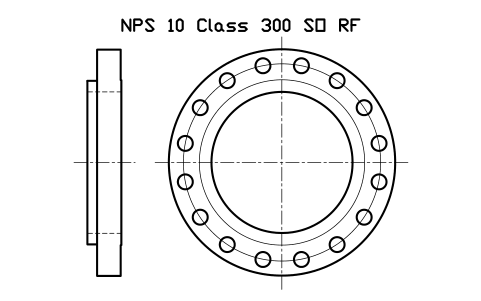
NPS 10 Class 300 SO RF
FLG_B165_SO_300_10Attributes
DESIGNATIONSTANDARDFLANGE_TYPEPRESSURE_CLASSFACEMATERIALSCHEDULEQTYPART_NOMANUFACTURERREMARKSDESC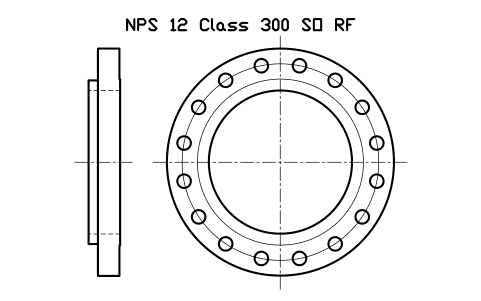
NPS 12 Class 300 SO RF
FLG_B165_SO_300_12Attributes
DESIGNATIONSTANDARDFLANGE_TYPEPRESSURE_CLASSFACEMATERIALSCHEDULEQTYPART_NOMANUFACTURERREMARKSDESC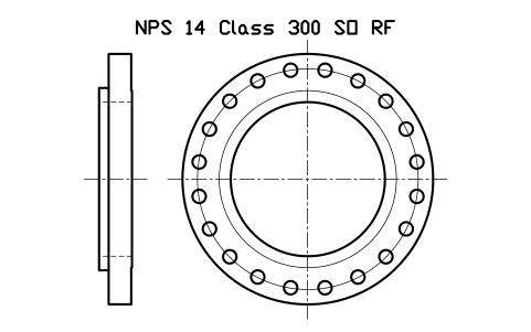
NPS 14 Class 300 SO RF
FLG_B165_SO_300_14Attributes
DESIGNATIONSTANDARDFLANGE_TYPEPRESSURE_CLASSFACEMATERIALSCHEDULEQTYPART_NOMANUFACTURERREMARKSDESC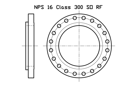
NPS 16 Class 300 SO RF
FLG_B165_SO_300_16Attributes
DESIGNATIONSTANDARDFLANGE_TYPEPRESSURE_CLASSFACEMATERIALSCHEDULEQTYPART_NOMANUFACTURERREMARKSDESC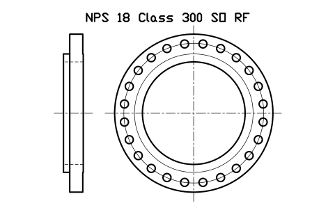
NPS 18 Class 300 SO RF
FLG_B165_SO_300_18Attributes
DESIGNATIONSTANDARDFLANGE_TYPEPRESSURE_CLASSFACEMATERIALSCHEDULEQTYPART_NOMANUFACTURERREMARKSDESC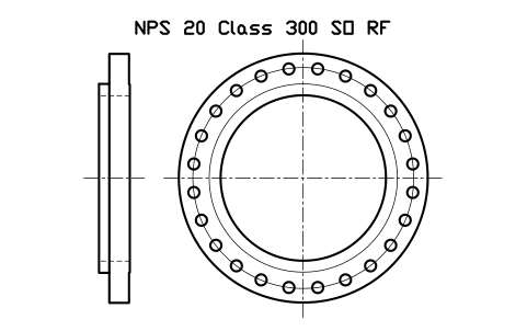
NPS 20 Class 300 SO RF
FLG_B165_SO_300_20Attributes
DESIGNATIONSTANDARDFLANGE_TYPEPRESSURE_CLASSFACEMATERIALSCHEDULEQTYPART_NOMANUFACTURERREMARKSDESC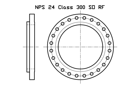
NPS 24 Class 300 SO RF
FLG_B165_SO_300_24Attributes
DESIGNATIONSTANDARDFLANGE_TYPEPRESSURE_CLASSFACEMATERIALSCHEDULEQTYPART_NOMANUFACTURERREMARKSDESC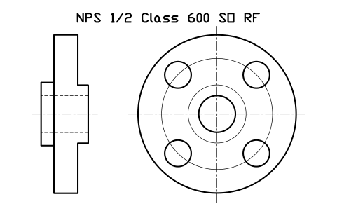
NPS 1/2 Class 600 SO RF
FLG_B165_SO_600_0.5Attributes
DESIGNATIONSTANDARDFLANGE_TYPEPRESSURE_CLASSFACEMATERIALSCHEDULEQTYPART_NOMANUFACTURERREMARKSDESC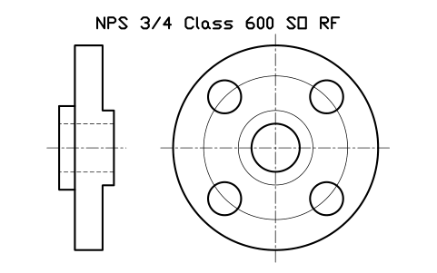
NPS 3/4 Class 600 SO RF
FLG_B165_SO_600_0.75Attributes
DESIGNATIONSTANDARDFLANGE_TYPEPRESSURE_CLASSFACEMATERIALSCHEDULEQTYPART_NOMANUFACTURERREMARKSDESC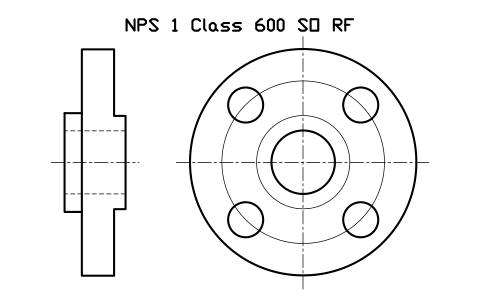
NPS 1 Class 600 SO RF
FLG_B165_SO_600_1Attributes
DESIGNATIONSTANDARDFLANGE_TYPEPRESSURE_CLASSFACEMATERIALSCHEDULEQTYPART_NOMANUFACTURERREMARKSDESC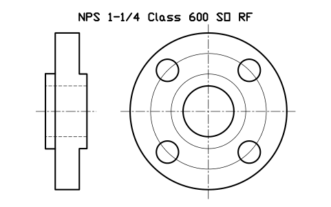
NPS 1-1/4 Class 600 SO RF
FLG_B165_SO_600_1.25Attributes
DESIGNATIONSTANDARDFLANGE_TYPEPRESSURE_CLASSFACEMATERIALSCHEDULEQTYPART_NOMANUFACTURERREMARKSDESC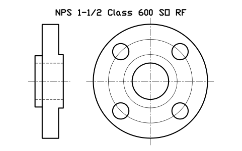
NPS 1-1/2 Class 600 SO RF
FLG_B165_SO_600_1.5Attributes
DESIGNATIONSTANDARDFLANGE_TYPEPRESSURE_CLASSFACEMATERIALSCHEDULEQTYPART_NOMANUFACTURERREMARKSDESC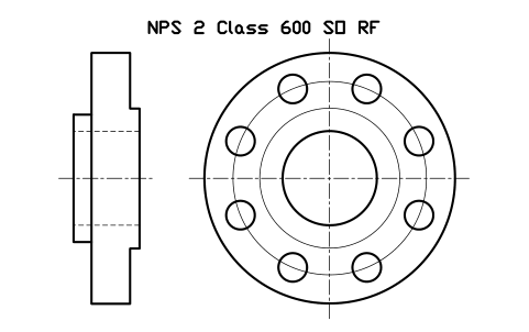
NPS 2 Class 600 SO RF
FLG_B165_SO_600_2Attributes
DESIGNATIONSTANDARDFLANGE_TYPEPRESSURE_CLASSFACEMATERIALSCHEDULEQTYPART_NOMANUFACTURERREMARKSDESC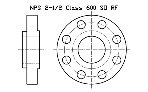
NPS 2-1/2 Class 600 SO RF
FLG_B165_SO_600_2.5Attributes
DESIGNATIONSTANDARDFLANGE_TYPEPRESSURE_CLASSFACEMATERIALSCHEDULEQTYPART_NOMANUFACTURERREMARKSDESC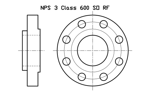
NPS 3 Class 600 SO RF
FLG_B165_SO_600_3Attributes
DESIGNATIONSTANDARDFLANGE_TYPEPRESSURE_CLASSFACEMATERIALSCHEDULEQTYPART_NOMANUFACTURERREMARKSDESC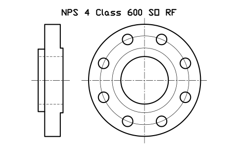
NPS 4 Class 600 SO RF
FLG_B165_SO_600_4Attributes
DESIGNATIONSTANDARDFLANGE_TYPEPRESSURE_CLASSFACEMATERIALSCHEDULEQTYPART_NOMANUFACTURERREMARKSDESC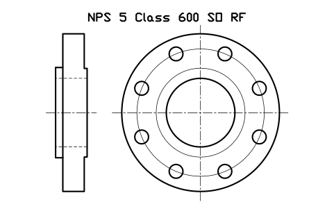
NPS 5 Class 600 SO RF
FLG_B165_SO_600_5Attributes
DESIGNATIONSTANDARDFLANGE_TYPEPRESSURE_CLASSFACEMATERIALSCHEDULEQTYPART_NOMANUFACTURERREMARKSDESC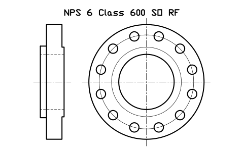
NPS 6 Class 600 SO RF
FLG_B165_SO_600_6Attributes
DESIGNATIONSTANDARDFLANGE_TYPEPRESSURE_CLASSFACEMATERIALSCHEDULEQTYPART_NOMANUFACTURERREMARKSDESC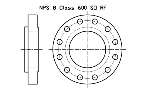
NPS 8 Class 600 SO RF
FLG_B165_SO_600_8Attributes
DESIGNATIONSTANDARDFLANGE_TYPEPRESSURE_CLASSFACEMATERIALSCHEDULEQTYPART_NOMANUFACTURERREMARKSDESC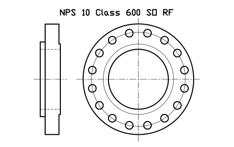
NPS 10 Class 600 SO RF
FLG_B165_SO_600_10Attributes
DESIGNATIONSTANDARDFLANGE_TYPEPRESSURE_CLASSFACEMATERIALSCHEDULEQTYPART_NOMANUFACTURERREMARKSDESC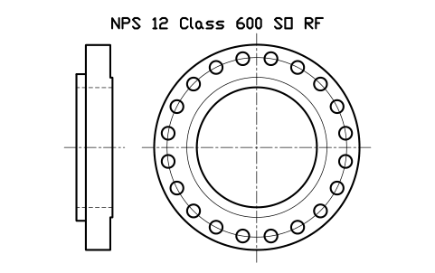
NPS 12 Class 600 SO RF
FLG_B165_SO_600_12Attributes
DESIGNATIONSTANDARDFLANGE_TYPEPRESSURE_CLASSFACEMATERIALSCHEDULEQTYPART_NOMANUFACTURERREMARKSDESC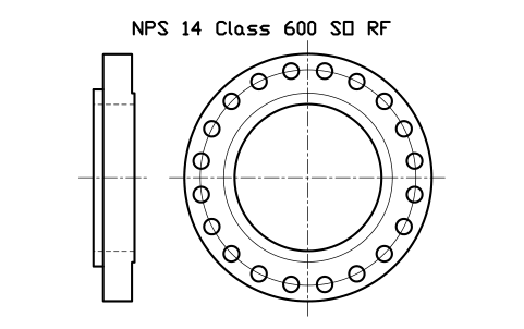
NPS 14 Class 600 SO RF
FLG_B165_SO_600_14Attributes
DESIGNATIONSTANDARDFLANGE_TYPEPRESSURE_CLASSFACEMATERIALSCHEDULEQTYPART_NOMANUFACTURERREMARKSDESC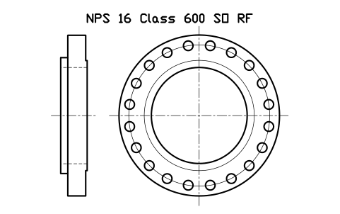
NPS 16 Class 600 SO RF
FLG_B165_SO_600_16Attributes
DESIGNATIONSTANDARDFLANGE_TYPEPRESSURE_CLASSFACEMATERIALSCHEDULEQTYPART_NOMANUFACTURERREMARKSDESC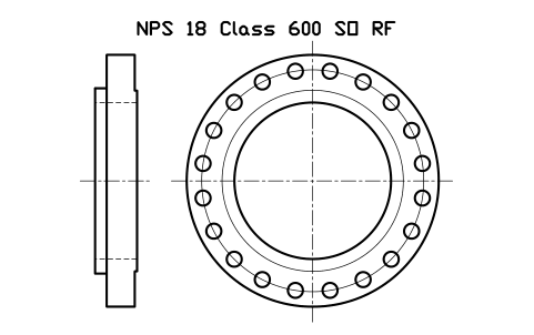
NPS 18 Class 600 SO RF
FLG_B165_SO_600_18Attributes
DESIGNATIONSTANDARDFLANGE_TYPEPRESSURE_CLASSFACEMATERIALSCHEDULEQTYPART_NOMANUFACTURERREMARKSDESC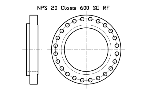
NPS 20 Class 600 SO RF
FLG_B165_SO_600_20Attributes
DESIGNATIONSTANDARDFLANGE_TYPEPRESSURE_CLASSFACEMATERIALSCHEDULEQTYPART_NOMANUFACTURERREMARKSDESC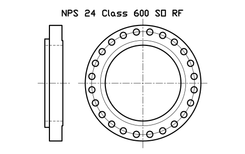
NPS 24 Class 600 SO RF
FLG_B165_SO_600_24Attributes
DESIGNATIONSTANDARDFLANGE_TYPEPRESSURE_CLASSFACEMATERIALSCHEDULEQTYPART_NOMANUFACTURERREMARKSDESC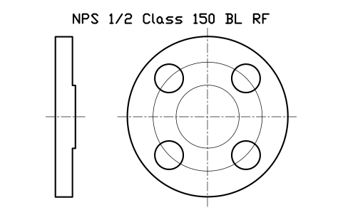
NPS 1/2 Class 150 BL RF
FLG_B165_BL_150_0.5Attributes
DESIGNATIONSTANDARDFLANGE_TYPEPRESSURE_CLASSFACEMATERIALSCHEDULEQTYPART_NOMANUFACTURERREMARKSDESC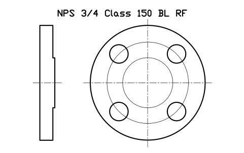
NPS 3/4 Class 150 BL RF
FLG_B165_BL_150_0.75Attributes
DESIGNATIONSTANDARDFLANGE_TYPEPRESSURE_CLASSFACEMATERIALSCHEDULEQTYPART_NOMANUFACTURERREMARKSDESC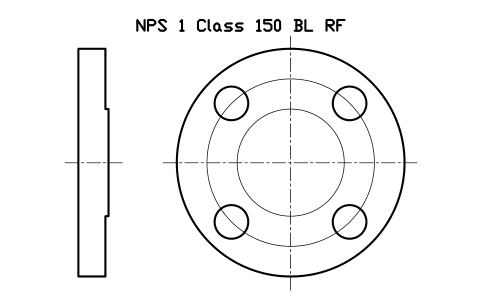
NPS 1 Class 150 BL RF
FLG_B165_BL_150_1Attributes
DESIGNATIONSTANDARDFLANGE_TYPEPRESSURE_CLASSFACEMATERIALSCHEDULEQTYPART_NOMANUFACTURERREMARKSDESC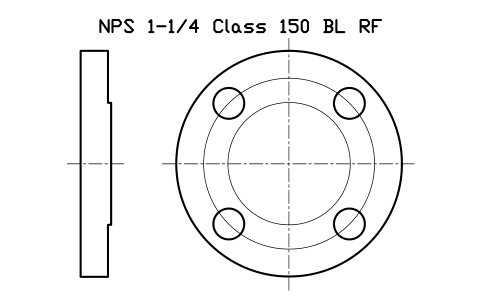
NPS 1-1/4 Class 150 BL RF
FLG_B165_BL_150_1.25Attributes
DESIGNATIONSTANDARDFLANGE_TYPEPRESSURE_CLASSFACEMATERIALSCHEDULEQTYPART_NOMANUFACTURERREMARKSDESC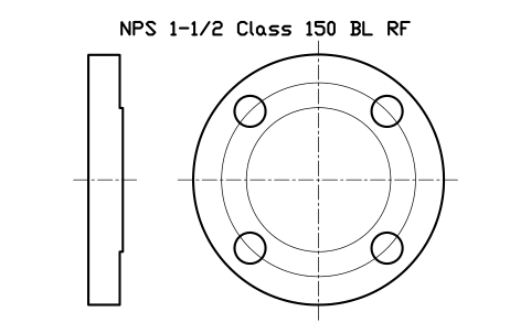
NPS 1-1/2 Class 150 BL RF
FLG_B165_BL_150_1.5Attributes
DESIGNATIONSTANDARDFLANGE_TYPEPRESSURE_CLASSFACEMATERIALSCHEDULEQTYPART_NOMANUFACTURERREMARKSDESC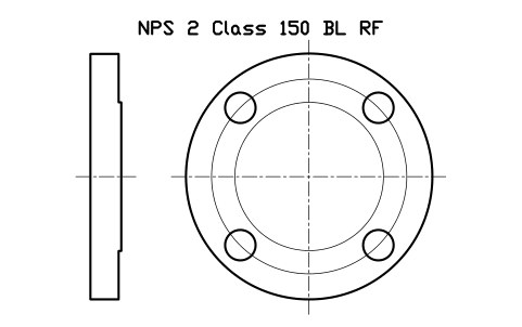
NPS 2 Class 150 BL RF
FLG_B165_BL_150_2Attributes
DESIGNATIONSTANDARDFLANGE_TYPEPRESSURE_CLASSFACEMATERIALSCHEDULEQTYPART_NOMANUFACTURERREMARKSDESC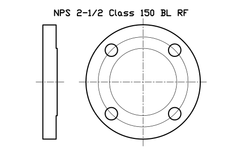
NPS 2-1/2 Class 150 BL RF
FLG_B165_BL_150_2.5Attributes
DESIGNATIONSTANDARDFLANGE_TYPEPRESSURE_CLASSFACEMATERIALSCHEDULEQTYPART_NOMANUFACTURERREMARKSDESC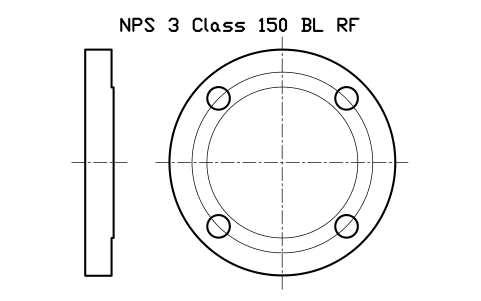
NPS 3 Class 150 BL RF
FLG_B165_BL_150_3Attributes
DESIGNATIONSTANDARDFLANGE_TYPEPRESSURE_CLASSFACEMATERIALSCHEDULEQTYPART_NOMANUFACTURERREMARKSDESC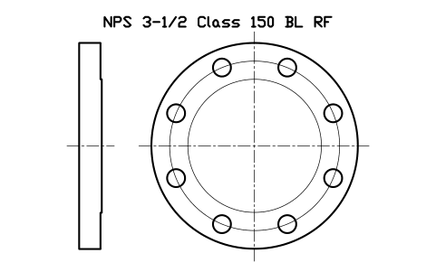
NPS 3-1/2 Class 150 BL RF
FLG_B165_BL_150_3.5Attributes
DESIGNATIONSTANDARDFLANGE_TYPEPRESSURE_CLASSFACEMATERIALSCHEDULEQTYPART_NOMANUFACTURERREMARKSDESC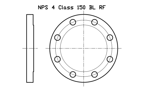
NPS 4 Class 150 BL RF
FLG_B165_BL_150_4Attributes
DESIGNATIONSTANDARDFLANGE_TYPEPRESSURE_CLASSFACEMATERIALSCHEDULEQTYPART_NOMANUFACTURERREMARKSDESC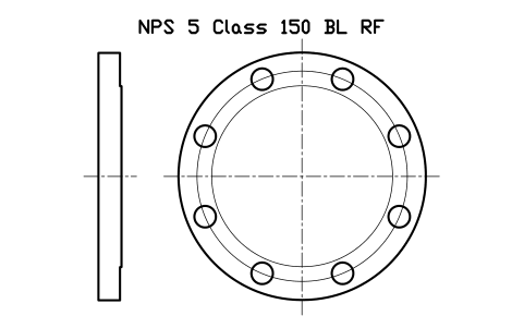
NPS 5 Class 150 BL RF
FLG_B165_BL_150_5Attributes
DESIGNATIONSTANDARDFLANGE_TYPEPRESSURE_CLASSFACEMATERIALSCHEDULEQTYPART_NOMANUFACTURERREMARKSDESC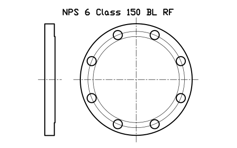
NPS 6 Class 150 BL RF
FLG_B165_BL_150_6Attributes
DESIGNATIONSTANDARDFLANGE_TYPEPRESSURE_CLASSFACEMATERIALSCHEDULEQTYPART_NOMANUFACTURERREMARKSDESC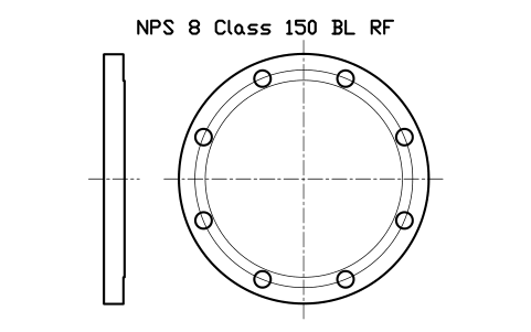
NPS 8 Class 150 BL RF
FLG_B165_BL_150_8Attributes
DESIGNATIONSTANDARDFLANGE_TYPEPRESSURE_CLASSFACEMATERIALSCHEDULEQTYPART_NOMANUFACTURERREMARKSDESC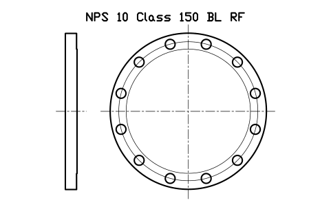
NPS 10 Class 150 BL RF
FLG_B165_BL_150_10Attributes
DESIGNATIONSTANDARDFLANGE_TYPEPRESSURE_CLASSFACEMATERIALSCHEDULEQTYPART_NOMANUFACTURERREMARKSDESC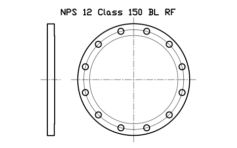
NPS 12 Class 150 BL RF
FLG_B165_BL_150_12Attributes
DESIGNATIONSTANDARDFLANGE_TYPEPRESSURE_CLASSFACEMATERIALSCHEDULEQTYPART_NOMANUFACTURERREMARKSDESC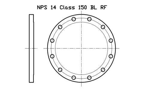
NPS 14 Class 150 BL RF
FLG_B165_BL_150_14Attributes
DESIGNATIONSTANDARDFLANGE_TYPEPRESSURE_CLASSFACEMATERIALSCHEDULEQTYPART_NOMANUFACTURERREMARKSDESC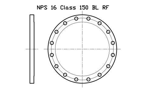
NPS 16 Class 150 BL RF
FLG_B165_BL_150_16Attributes
DESIGNATIONSTANDARDFLANGE_TYPEPRESSURE_CLASSFACEMATERIALSCHEDULEQTYPART_NOMANUFACTURERREMARKSDESC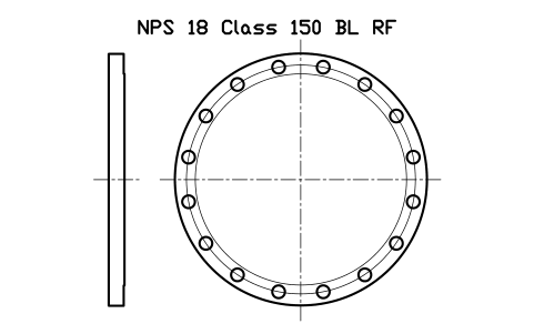
NPS 18 Class 150 BL RF
FLG_B165_BL_150_18Attributes
DESIGNATIONSTANDARDFLANGE_TYPEPRESSURE_CLASSFACEMATERIALSCHEDULEQTYPART_NOMANUFACTURERREMARKSDESC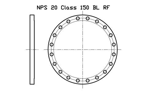
NPS 20 Class 150 BL RF
FLG_B165_BL_150_20Attributes
DESIGNATIONSTANDARDFLANGE_TYPEPRESSURE_CLASSFACEMATERIALSCHEDULEQTYPART_NOMANUFACTURERREMARKSDESC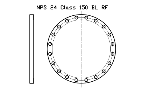
NPS 24 Class 150 BL RF
FLG_B165_BL_150_24Attributes
DESIGNATIONSTANDARDFLANGE_TYPEPRESSURE_CLASSFACEMATERIALSCHEDULEQTYPART_NOMANUFACTURERREMARKSDESC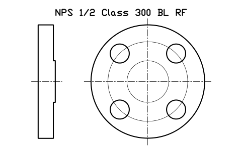
NPS 1/2 Class 300 BL RF
FLG_B165_BL_300_0.5Attributes
DESIGNATIONSTANDARDFLANGE_TYPEPRESSURE_CLASSFACEMATERIALSCHEDULEQTYPART_NOMANUFACTURERREMARKSDESC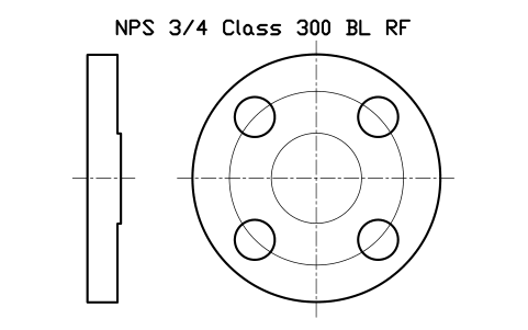
NPS 3/4 Class 300 BL RF
FLG_B165_BL_300_0.75Attributes
DESIGNATIONSTANDARDFLANGE_TYPEPRESSURE_CLASSFACEMATERIALSCHEDULEQTYPART_NOMANUFACTURERREMARKSDESC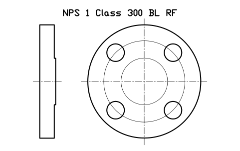
NPS 1 Class 300 BL RF
FLG_B165_BL_300_1Attributes
DESIGNATIONSTANDARDFLANGE_TYPEPRESSURE_CLASSFACEMATERIALSCHEDULEQTYPART_NOMANUFACTURERREMARKSDESC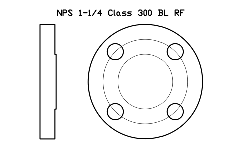
NPS 1-1/4 Class 300 BL RF
FLG_B165_BL_300_1.25Attributes
DESIGNATIONSTANDARDFLANGE_TYPEPRESSURE_CLASSFACEMATERIALSCHEDULEQTYPART_NOMANUFACTURERREMARKSDESC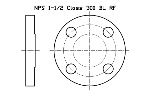
NPS 1-1/2 Class 300 BL RF
FLG_B165_BL_300_1.5Attributes
DESIGNATIONSTANDARDFLANGE_TYPEPRESSURE_CLASSFACEMATERIALSCHEDULEQTYPART_NOMANUFACTURERREMARKSDESC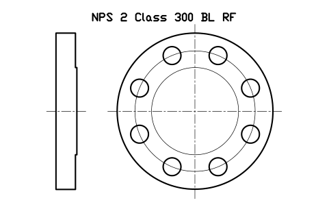
NPS 2 Class 300 BL RF
FLG_B165_BL_300_2Attributes
DESIGNATIONSTANDARDFLANGE_TYPEPRESSURE_CLASSFACEMATERIALSCHEDULEQTYPART_NOMANUFACTURERREMARKSDESC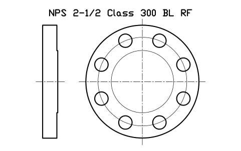
NPS 2-1/2 Class 300 BL RF
FLG_B165_BL_300_2.5Attributes
DESIGNATIONSTANDARDFLANGE_TYPEPRESSURE_CLASSFACEMATERIALSCHEDULEQTYPART_NOMANUFACTURERREMARKSDESC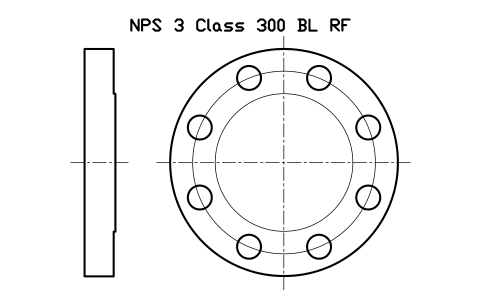
NPS 3 Class 300 BL RF
FLG_B165_BL_300_3Attributes
DESIGNATIONSTANDARDFLANGE_TYPEPRESSURE_CLASSFACEMATERIALSCHEDULEQTYPART_NOMANUFACTURERREMARKSDESC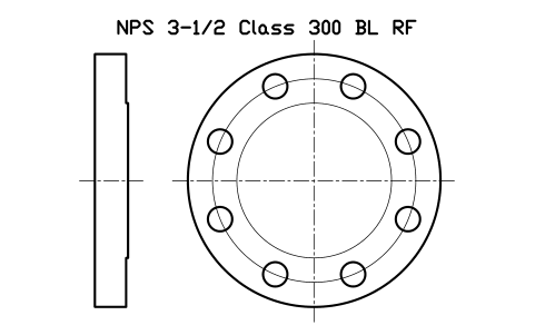
NPS 3-1/2 Class 300 BL RF
FLG_B165_BL_300_3.5Attributes
DESIGNATIONSTANDARDFLANGE_TYPEPRESSURE_CLASSFACEMATERIALSCHEDULEQTYPART_NOMANUFACTURERREMARKSDESC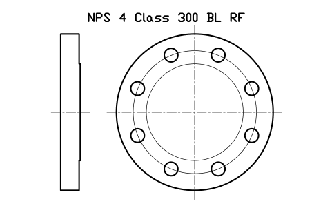
NPS 4 Class 300 BL RF
FLG_B165_BL_300_4Attributes
DESIGNATIONSTANDARDFLANGE_TYPEPRESSURE_CLASSFACEMATERIALSCHEDULEQTYPART_NOMANUFACTURERREMARKSDESC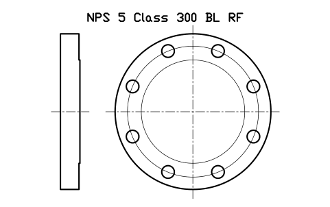
NPS 5 Class 300 BL RF
FLG_B165_BL_300_5Attributes
DESIGNATIONSTANDARDFLANGE_TYPEPRESSURE_CLASSFACEMATERIALSCHEDULEQTYPART_NOMANUFACTURERREMARKSDESC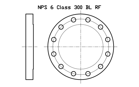
NPS 6 Class 300 BL RF
FLG_B165_BL_300_6Attributes
DESIGNATIONSTANDARDFLANGE_TYPEPRESSURE_CLASSFACEMATERIALSCHEDULEQTYPART_NOMANUFACTURERREMARKSDESC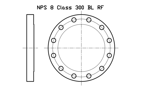
NPS 8 Class 300 BL RF
FLG_B165_BL_300_8Attributes
DESIGNATIONSTANDARDFLANGE_TYPEPRESSURE_CLASSFACEMATERIALSCHEDULEQTYPART_NOMANUFACTURERREMARKSDESC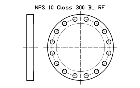
NPS 10 Class 300 BL RF
FLG_B165_BL_300_10Attributes
DESIGNATIONSTANDARDFLANGE_TYPEPRESSURE_CLASSFACEMATERIALSCHEDULEQTYPART_NOMANUFACTURERREMARKSDESC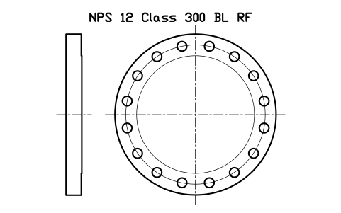
NPS 12 Class 300 BL RF
FLG_B165_BL_300_12Attributes
DESIGNATIONSTANDARDFLANGE_TYPEPRESSURE_CLASSFACEMATERIALSCHEDULEQTYPART_NOMANUFACTURERREMARKSDESC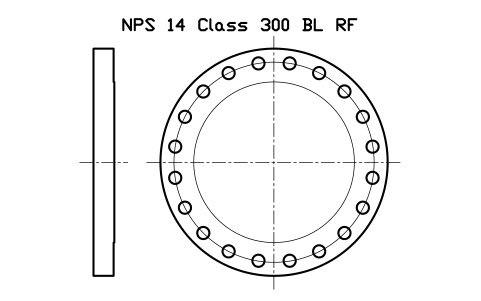
NPS 14 Class 300 BL RF
FLG_B165_BL_300_14Attributes
DESIGNATIONSTANDARDFLANGE_TYPEPRESSURE_CLASSFACEMATERIALSCHEDULEQTYPART_NOMANUFACTURERREMARKSDESC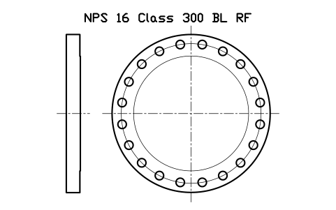
NPS 16 Class 300 BL RF
FLG_B165_BL_300_16Attributes
DESIGNATIONSTANDARDFLANGE_TYPEPRESSURE_CLASSFACEMATERIALSCHEDULEQTYPART_NOMANUFACTURERREMARKSDESC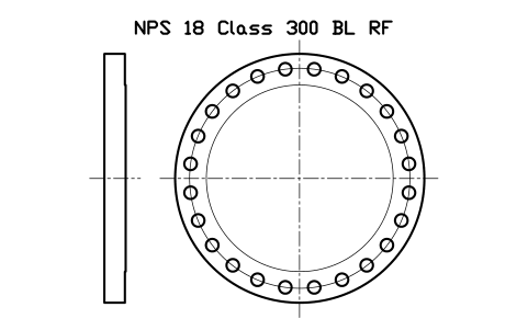
NPS 18 Class 300 BL RF
FLG_B165_BL_300_18Attributes
DESIGNATIONSTANDARDFLANGE_TYPEPRESSURE_CLASSFACEMATERIALSCHEDULEQTYPART_NOMANUFACTURERREMARKSDESC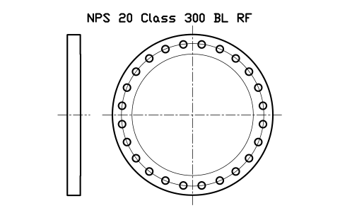
NPS 20 Class 300 BL RF
FLG_B165_BL_300_20Attributes
DESIGNATIONSTANDARDFLANGE_TYPEPRESSURE_CLASSFACEMATERIALSCHEDULEQTYPART_NOMANUFACTURERREMARKSDESC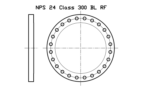
NPS 24 Class 300 BL RF
FLG_B165_BL_300_24Attributes
DESIGNATIONSTANDARDFLANGE_TYPEPRESSURE_CLASSFACEMATERIALSCHEDULEQTYPART_NOMANUFACTURERREMARKSDESC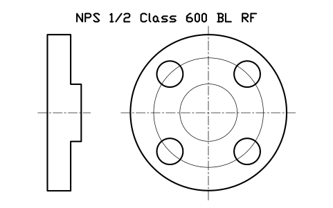
NPS 1/2 Class 600 BL RF
FLG_B165_BL_600_0.5Attributes
DESIGNATIONSTANDARDFLANGE_TYPEPRESSURE_CLASSFACEMATERIALSCHEDULEQTYPART_NOMANUFACTURERREMARKSDESC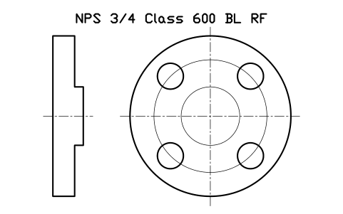
NPS 3/4 Class 600 BL RF
FLG_B165_BL_600_0.75Attributes
DESIGNATIONSTANDARDFLANGE_TYPEPRESSURE_CLASSFACEMATERIALSCHEDULEQTYPART_NOMANUFACTURERREMARKSDESC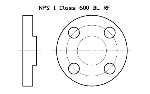
NPS 1 Class 600 BL RF
FLG_B165_BL_600_1Attributes
DESIGNATIONSTANDARDFLANGE_TYPEPRESSURE_CLASSFACEMATERIALSCHEDULEQTYPART_NOMANUFACTURERREMARKSDESC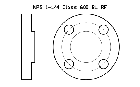
NPS 1-1/4 Class 600 BL RF
FLG_B165_BL_600_1.25Attributes
DESIGNATIONSTANDARDFLANGE_TYPEPRESSURE_CLASSFACEMATERIALSCHEDULEQTYPART_NOMANUFACTURERREMARKSDESC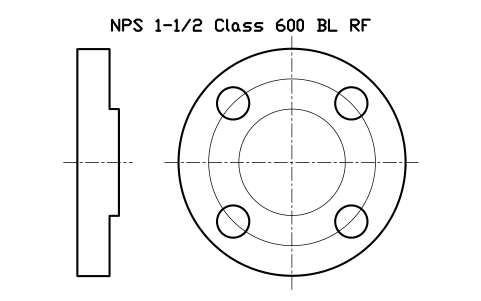
NPS 1-1/2 Class 600 BL RF
FLG_B165_BL_600_1.5Attributes
DESIGNATIONSTANDARDFLANGE_TYPEPRESSURE_CLASSFACEMATERIALSCHEDULEQTYPART_NOMANUFACTURERREMARKSDESC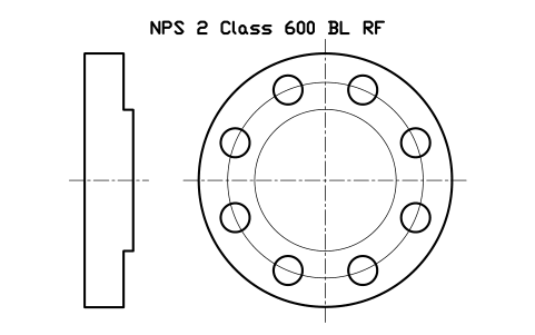
NPS 2 Class 600 BL RF
FLG_B165_BL_600_2Attributes
DESIGNATIONSTANDARDFLANGE_TYPEPRESSURE_CLASSFACEMATERIALSCHEDULEQTYPART_NOMANUFACTURERREMARKSDESC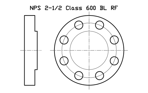
NPS 2-1/2 Class 600 BL RF
FLG_B165_BL_600_2.5Attributes
DESIGNATIONSTANDARDFLANGE_TYPEPRESSURE_CLASSFACEMATERIALSCHEDULEQTYPART_NOMANUFACTURERREMARKSDESC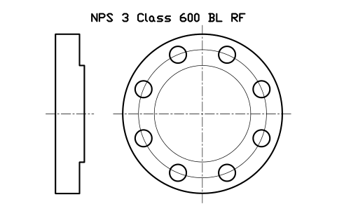
NPS 3 Class 600 BL RF
FLG_B165_BL_600_3Attributes
DESIGNATIONSTANDARDFLANGE_TYPEPRESSURE_CLASSFACEMATERIALSCHEDULEQTYPART_NOMANUFACTURERREMARKSDESC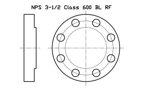
NPS 3-1/2 Class 600 BL RF
FLG_B165_BL_600_3.5Attributes
DESIGNATIONSTANDARDFLANGE_TYPEPRESSURE_CLASSFACEMATERIALSCHEDULEQTYPART_NOMANUFACTURERREMARKSDESC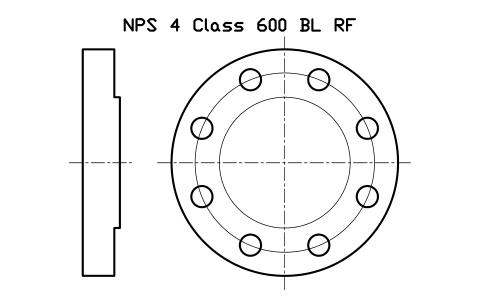
NPS 4 Class 600 BL RF
FLG_B165_BL_600_4Attributes
DESIGNATIONSTANDARDFLANGE_TYPEPRESSURE_CLASSFACEMATERIALSCHEDULEQTYPART_NOMANUFACTURERREMARKSDESC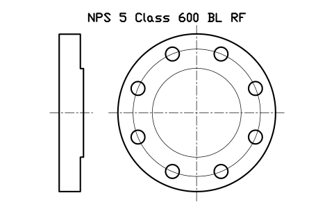
NPS 5 Class 600 BL RF
FLG_B165_BL_600_5Attributes
DESIGNATIONSTANDARDFLANGE_TYPEPRESSURE_CLASSFACEMATERIALSCHEDULEQTYPART_NOMANUFACTURERREMARKSDESC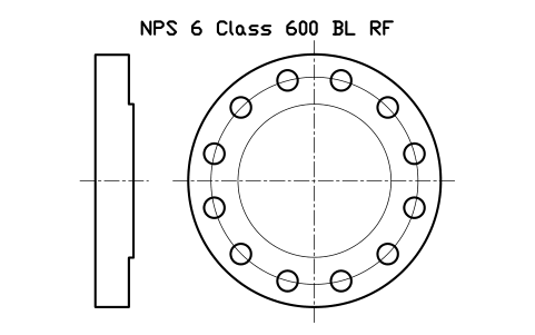
NPS 6 Class 600 BL RF
FLG_B165_BL_600_6Attributes
DESIGNATIONSTANDARDFLANGE_TYPEPRESSURE_CLASSFACEMATERIALSCHEDULEQTYPART_NOMANUFACTURERREMARKSDESC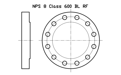
NPS 8 Class 600 BL RF
FLG_B165_BL_600_8Attributes
DESIGNATIONSTANDARDFLANGE_TYPEPRESSURE_CLASSFACEMATERIALSCHEDULEQTYPART_NOMANUFACTURERREMARKSDESC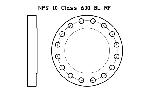
NPS 10 Class 600 BL RF
FLG_B165_BL_600_10Attributes
DESIGNATIONSTANDARDFLANGE_TYPEPRESSURE_CLASSFACEMATERIALSCHEDULEQTYPART_NOMANUFACTURERREMARKSDESC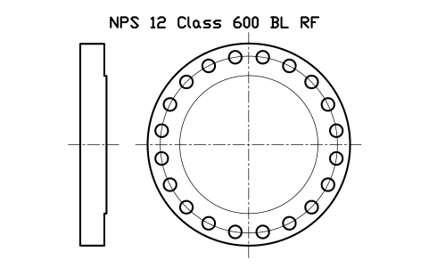
NPS 12 Class 600 BL RF
FLG_B165_BL_600_12Attributes
DESIGNATIONSTANDARDFLANGE_TYPEPRESSURE_CLASSFACEMATERIALSCHEDULEQTYPART_NOMANUFACTURERREMARKSDESC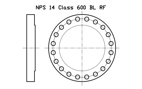
NPS 14 Class 600 BL RF
FLG_B165_BL_600_14Attributes
DESIGNATIONSTANDARDFLANGE_TYPEPRESSURE_CLASSFACEMATERIALSCHEDULEQTYPART_NOMANUFACTURERREMARKSDESC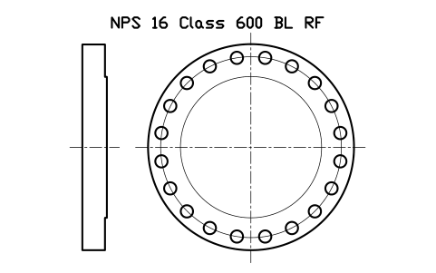
NPS 16 Class 600 BL RF
FLG_B165_BL_600_16Attributes
DESIGNATIONSTANDARDFLANGE_TYPEPRESSURE_CLASSFACEMATERIALSCHEDULEQTYPART_NOMANUFACTURERREMARKSDESC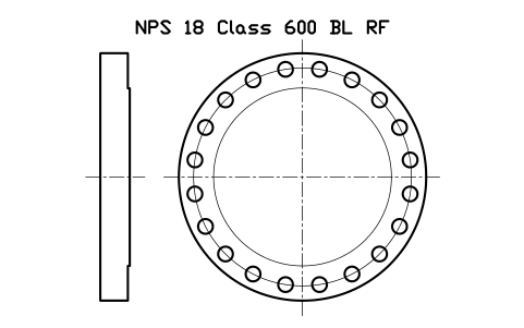
NPS 18 Class 600 BL RF
FLG_B165_BL_600_18Attributes
DESIGNATIONSTANDARDFLANGE_TYPEPRESSURE_CLASSFACEMATERIALSCHEDULEQTYPART_NOMANUFACTURERREMARKSDESC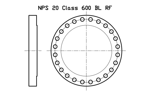
NPS 20 Class 600 BL RF
FLG_B165_BL_600_20Attributes
DESIGNATIONSTANDARDFLANGE_TYPEPRESSURE_CLASSFACEMATERIALSCHEDULEQTYPART_NOMANUFACTURERREMARKSDESC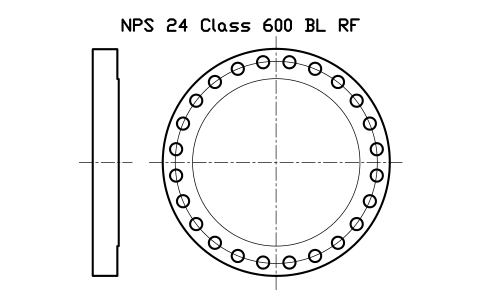
NPS 24 Class 600 BL RF
FLG_B165_BL_600_24Attributes
DESIGNATIONSTANDARDFLANGE_TYPEPRESSURE_CLASSFACEMATERIALSCHEDULEQTYPART_NOMANUFACTURERREMARKSDESC
Missing a symbol? Tell us which one.
Attributes for parts lists
Every block has a visible DESIGNATION attribute (for example NPS 6 Class 150 WN RF) above the flange; its text grows with the size of the flange. The data for a flange list are invisible attributes: STANDARD, FLANGE_TYPE, PRESSURE_CLASS, FACE, MATERIAL, SCHEDULE, QTY, PART_NO, MANUFACTURER and REMARKS.
How to use the library
- Unzip the file and open the DWG. Copy the symbols you need into your plan, or drag the blocks in from DesignCenter (ADCENTER).
- The blocks are drawn at real size in inches, 1 drawing unit = 1 inch, and the drawing units are set to inches. In a millimetre drawing insert them with a scale factor of 25.4.
- The insertion point is the sealing face on the pipe axis, the top of the raised face, with the flange behind it to the left and the face view to the right. Rotate or mirror the block to put the flange on your pipe.
- Weld neck flanges are bored for the standard wall, STD for Class 150 and 300 and XS for Class 600. The bore follows your pipe schedule, so change the bore circle and the hidden lines if your line has another wall.
About ASME B16.5 and the dimensions
Flange diameter, raised face diameter, thickness, bolt circle and bolt holes follow the tables of ASME B16.5; they agree in several published tables. The raised face is 1/16 in for Class 150 and 300, included in the thickness, and 1/4 in for Class 600, added to it. Hub diameter and length come from the published weld neck and slip-on tables.
The blocks are our own drawings, not copies of the standard, and the library is not certified. Dimensions are nominal, without tolerances. Slip-on flanges of Class 600 in NPS 3-1/2 are not in the published tables and are left out. Check the dimensions against the edition of ASME B16.5 your project uses.
Frequently asked questions
- Are these flanges to ASME B16.5?
- Yes. Flange diameter, raised face, thickness, bolt circle and bolt holes come from the tables of the standard, and they agree in several published tables. They are nominal drawing dimensions, without tolerances.
- Which bore do the weld neck flanges have?
- The bore of the standard wall: STD for Class 150 and 300, XS for Class 600. A weld neck flange is bored to match the pipe, so change the bore if your line has another schedule.
- Can I use the symbols in commercial projects?
- Yes. They are free to use and modify in your own projects, including commercial ones. They are provided as is, without warranty. Please do not redistribute or resell the library; see the library terms.
- Can I change a symbol or add attributes?
- Yes. Open the DWG, edit a block with BEDIT to change it or add attributes, and save. To update drawings that already contain the block, run ATTSYNC or replace the block. Make a backup first: attribute values can be lost if ATTSYNC is used carelessly.
- Where do I find a ready-made set of these symbols for AutoCAD?
- AutoCAD itself ships only a small set of sample blocks, so a full symbol set has to come from a library. Download the ZIP on this page and open the DWG: every symbol is a block. Insert one with INSERT (Blocks palette, Libraries tab, then pick the DWG) or drag it from DesignCenter (ADCENTER). You can also download a single symbol on its own.