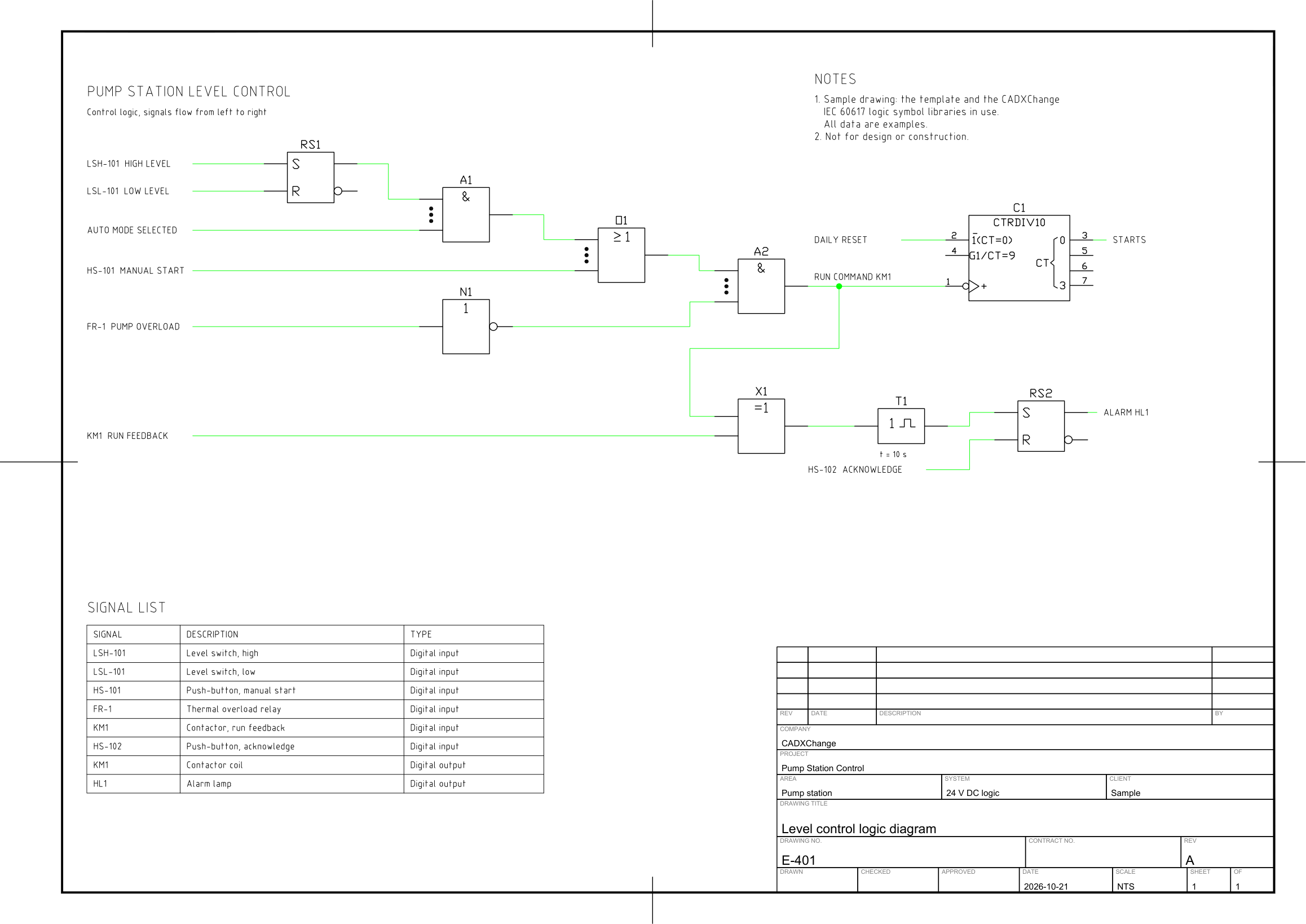
ResourcesElectrical schematic symbolsLogic and PLC diagram
PLC I/O wiring
Pump station PLC wiring: power supply and CPU, a digital input module with four field devices, a relay output module with four loads, an analogue input module with two transmitters, and the 24 V DC and 0 V rails.
Free to use and modify in your own projects, including commercial ones. The ZIP holds the sample drawing, a template, a plot style table and a README; no add-in needed. The data in the drawing is made up, so it is not for design or construction. Provided as is, without warranty. Library terms (CXL-1.0)
Version 1.0 · updated October 21, 2026
This sample uses these resources
The symbols are blocks from our own libraries, with their attributes filled in. The sheet and its title block come from our ISO A3 title block template. Download them to draw your own diagrams.
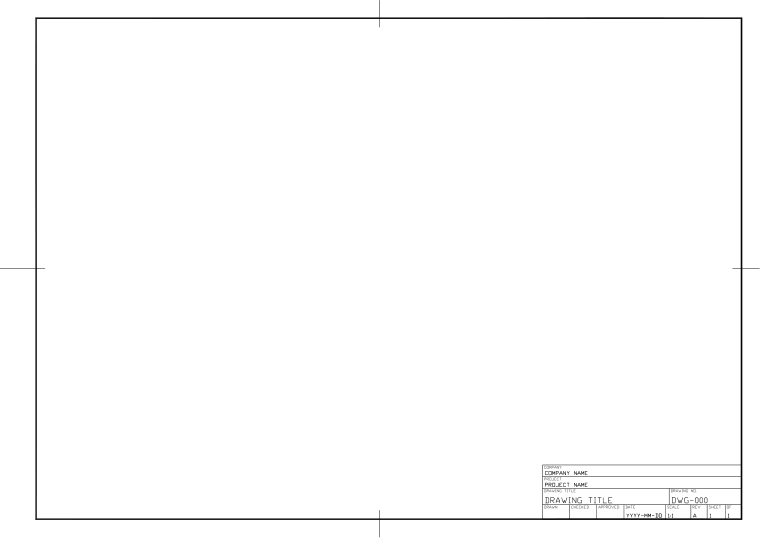
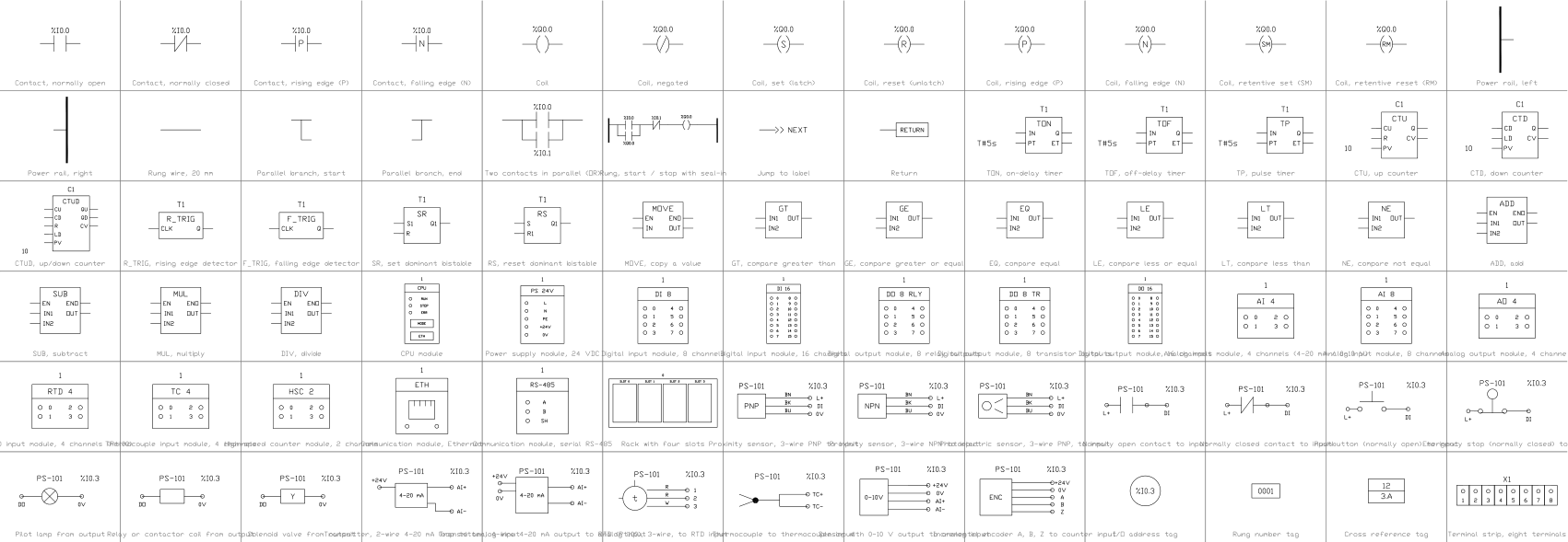
Layers, styles and sheet setup are the same for every drawing in the series; they are described on the series page: Logic and PLC diagram
Title block fields
The attributes of the title block. Double-click it to fill them in, or write them for a whole set of drawings with BlockSync.
| Attribute | Field on the sheet | Value in this sample |
|---|---|---|
| COMPANY | COMPANY | CADXChange |
| PROJECT | PROJECT | Pump Station Control |
| AREA | AREA | Pump station |
| SYSTEM | SYSTEM | 24 V DC |
| CLIENT | CLIENT | Sample |
| TITLE | DRAWING TITLE | PLC input and output wiring |
| DRAWING_NO | DRAWING NO. | E-402 |
| CONTRACT_NO | CONTRACT NO. | — |
| REV | REV | A |
| DRAWN | DRAWN | — |
| CHECKED | CHECKED | — |
| APPROVED | APPROVED | — |
| DATE | DATE | 2026-10-21 |
| SCALE | SCALE | NTS |
| SHEET | SHEET | 1 |
| SHEET_OF | OF | 1 |
Revision table: R1 to R4, each with REV, DATE, DESCRIPTION and BY (16 attributes, empty in this sample).
Blocks in the drawing
The equipment list of the drawing: block name, symbol and how many times it is placed. BlockSync exports the same list from your own drawings.
| Symbol | Block | Placed |
|---|---|---|
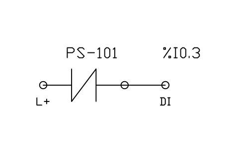 Normally closed contact to input | PLC_FIELD_CONTACT_NC | 2 |
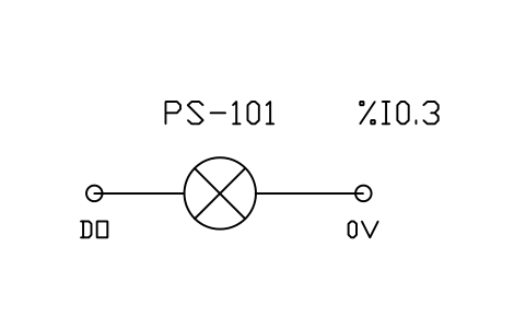 Pilot lamp from output | PLC_FIELD_LAMP | 2 |
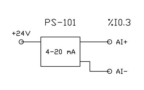 Transmitter, 2-wire 4-20 mA loop to analog input | PLC_FIELD_4_20MA_2WIRE | 2 |
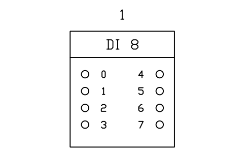 Digital input module, 8 channels | PLC_MOD_DI8 | 1 |
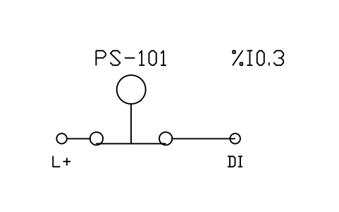 Emergency stop (normally closed) to input | PLC_FIELD_ESTOP | 1 |
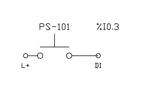 Pushbutton (normally open) to input | PLC_FIELD_PUSHBUTTON | 1 |
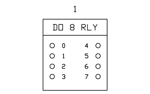 Digital output module, 8 relay outputs | PLC_MOD_DO8_RELAY | 1 |
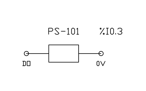 Relay or contactor coil from output | PLC_FIELD_COIL | 1 |
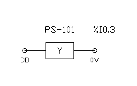 Solenoid valve from output | PLC_FIELD_SOLENOID | 1 |
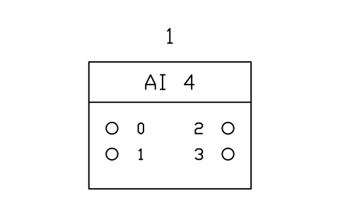 Analog input module, 4 channels (4-20 mA / 0-10 V) | PLC_MOD_AI4 | 1 |
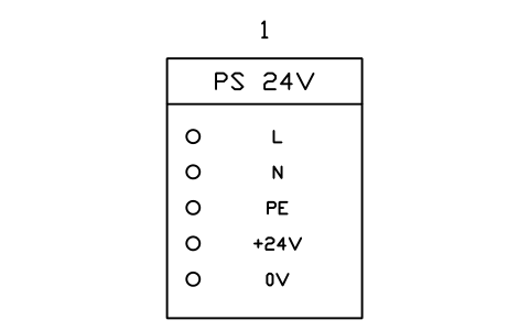 Power supply module, 24 VDC | PLC_MOD_PSU | 1 |
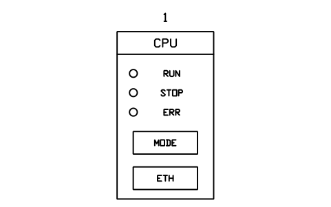 CPU module | PLC_MOD_CPU | 1 |
Equipment schedule
One row per placed symbol, read from the attributes of the blocks in the drawing: what is shown on the sheet, and the schedule attributes that were filled in but are not shown. BlockSync exports these same attributes from your own drawings.
| Tag | Description | Shown on the sheet | Filled in, not shown |
|---|---|---|---|
| 1 | Digital input module, 8 channelsPLC_MOD_DI8 | MODULE_TYPE = Digital inputADDRESS_START = I0.0CHANNELS = 8SIGNAL = 24 V DC | |
| SB1 | Emergency stop (normally closed) to inputPLC_FIELD_ESTOP | ADDRESS = I0.0 | DESCRIPTION = Emergency stop, normally closedCABLE = 2x0.75 mm2 |
| SB2 | Normally closed contact to inputPLC_FIELD_CONTACT_NC | ADDRESS = I0.1 | DESCRIPTION = Stop, normally closedCABLE = 2x0.75 mm2 |
| SB3 | Pushbutton (normally open) to inputPLC_FIELD_PUSHBUTTON | ADDRESS = I0.2 | DESCRIPTION = Start, normally openCABLE = 2x0.75 mm2 |
| FR1 | Normally closed contact to inputPLC_FIELD_CONTACT_NC | ADDRESS = I0.3 | DESCRIPTION = Pump overload, normally closedCABLE = 2x0.75 mm2 |
| 2 | Digital output module, 8 relay outputsPLC_MOD_DO8_RELAY | MODULE_TYPE = Digital output, relayADDRESS_START = Q0.0CHANNELS = 8SIGNAL = 24 V DC, 2 A | |
| KM1 | Relay or contactor coil from outputPLC_FIELD_COIL | ADDRESS = Q0.4 | DESCRIPTION = Pump contactor coilCABLE = 2x0.75 mm2 |
| HL1 | Pilot lamp from outputPLC_FIELD_LAMP | ADDRESS = Q0.5 | DESCRIPTION = Run lamp, greenCABLE = 2x0.75 mm2 |
| HL2 | Pilot lamp from outputPLC_FIELD_LAMP | ADDRESS = Q0.6 | DESCRIPTION = Alarm lamp, redCABLE = 2x0.75 mm2 |
| YV1 | Solenoid valve from outputPLC_FIELD_SOLENOID | ADDRESS = Q0.7 | DESCRIPTION = Inlet valve solenoidCABLE = 2x0.75 mm2 |
| 3 | Analog input module, 4 channels (4-20 mA / 0-10 V)PLC_MOD_AI4 | MODULE_TYPE = Analogue inputADDRESS_START = IW0CHANNELS = 4SIGNAL = 4-20 mA | |
| PT101 | Transmitter, 2-wire 4-20 mA loop to analog inputPLC_FIELD_4_20MA_2WIRE | ADDRESS = IW0 | DESCRIPTION = Discharge pressure transmitterCABLE = 2x0.75 mm2, shielded |
| LT101 | Transmitter, 2-wire 4-20 mA loop to analog inputPLC_FIELD_4_20MA_2WIRE | ADDRESS = IW1 | DESCRIPTION = Wet well level transmitterCABLE = 2x0.75 mm2, shielded |
| PS | Power supply module, 24 VDCPLC_MOD_PSU | INPUT = 230 V ACOUTPUT = 24 V DC, 10 A | |
| 0 | CPU modulePLC_MOD_CPU | MODULE_TYPE = CPU |
Manufacturer, model and remarks are left empty on every block, ready for your data. The values are examples.