
IEC 60617 vs ANSI/IEEE 315: electrical symbols side by side
Electrical drawings in North America and in the rest of the world often use different symbols for the same device. This page puts the two sets next to each other: the IEC 60617 form on the left and the ANSI/IEEE 315 form on the right, taken from our free DWG libraries. Click a symbol to open its page and download the block.
Which one should you use?
Use the standard that your customer, contract or company drawing standard names. If none is named, use the one the people who will read and maintain the drawing already know: IEC 60617 in most of the world, ANSI/IEEE 315 in North America.
Keep one set per drawing. If a project forces you to mix them, show both forms in the legend so nobody has to guess.
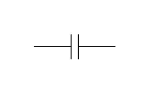
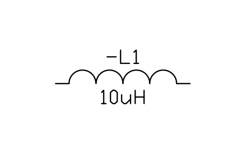
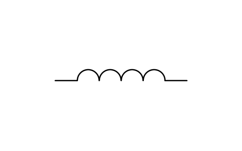
Resistors, capacitors and inductors
IEC 60617
ANSI/IEEE 315
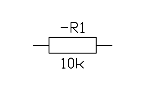
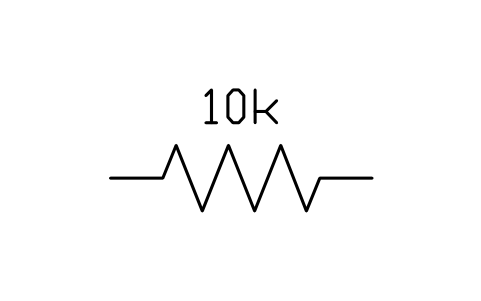
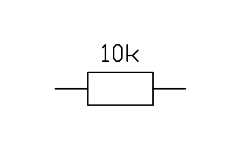
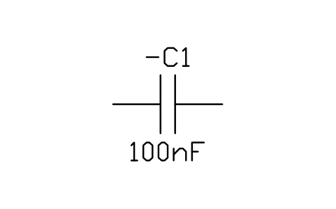
Transformers, motors and generators
IEC 60617
ANSI/IEEE 315
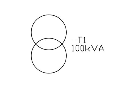 Transformer (circles)
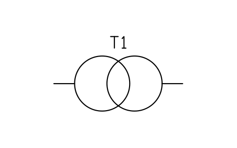 Transformer, two windings (circle form)
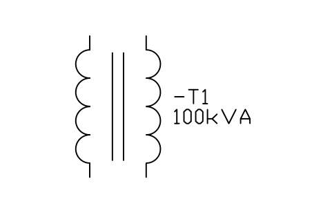 Transformer (windings)
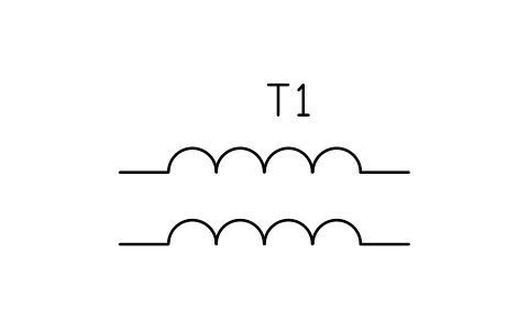 Transformer, two windings (coil form)
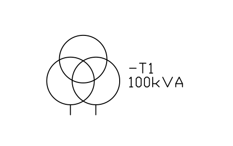 Transformer, three windings
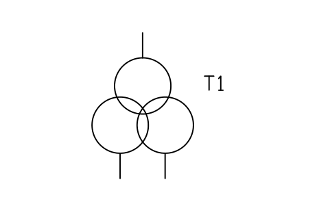 Transformer, three windings (circle form)
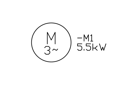 Motor, three-phase
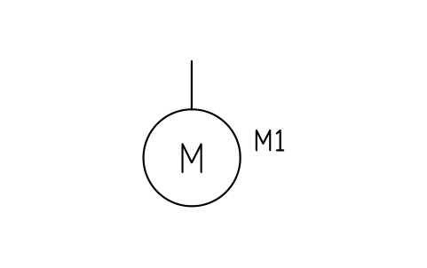 Motor, general
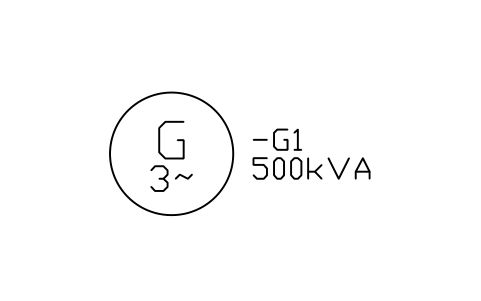 Generator, three-phase
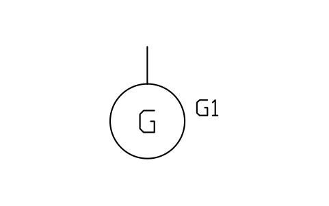 Generator, general
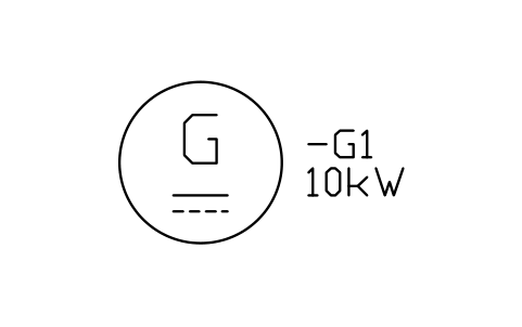 Generator, DC
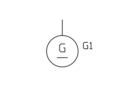 Generator, direct current
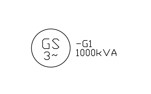 Generator, synchronous
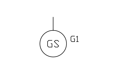 Generator, synchronous
Contacts, pushbuttons, coils and contactors
IEC 60617
ANSI/IEEE 315
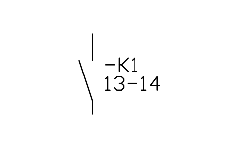 Make contact (NO)
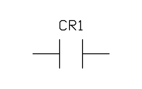 Contact, normally open (make)
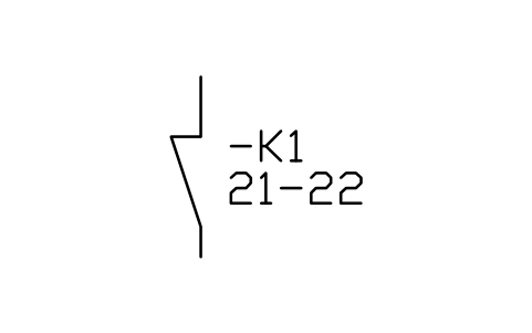 Break contact (NC)
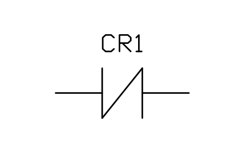 Contact, normally closed (break)
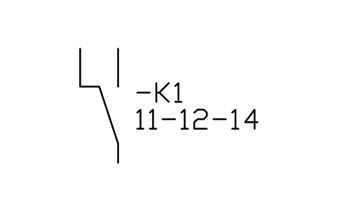 Changeover contact
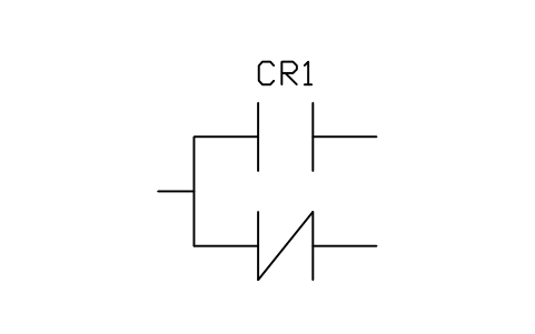 Contact, transfer (one open, one closed)
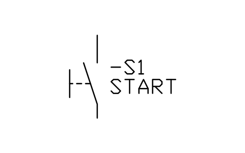 Push-button, NO
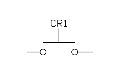 Pushbutton, circuit closing (normally open)
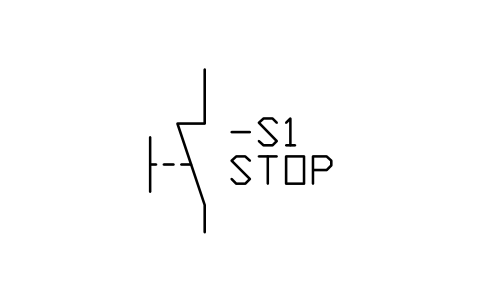 Push-button, NC
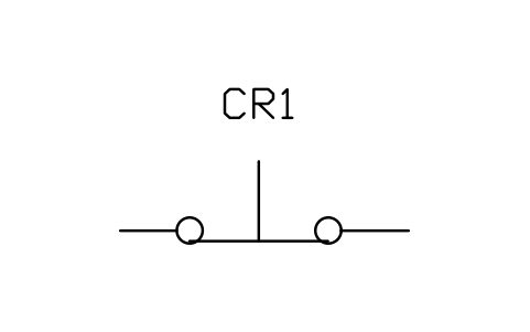 Pushbutton, circuit opening (normally closed)
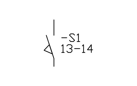 Limit switch, NO
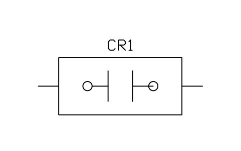 Limit switch, circuit closing (normally open)
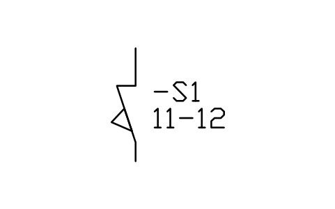 Limit switch, NC
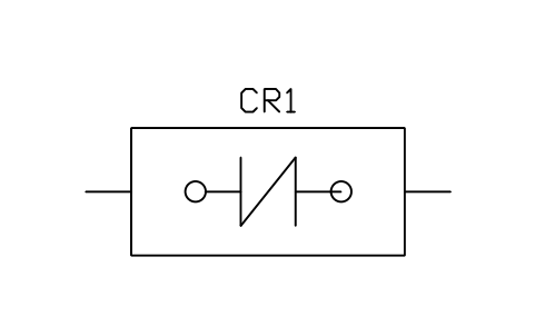 Limit switch, circuit opening (normally closed)
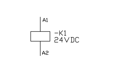 Relay / contactor coil
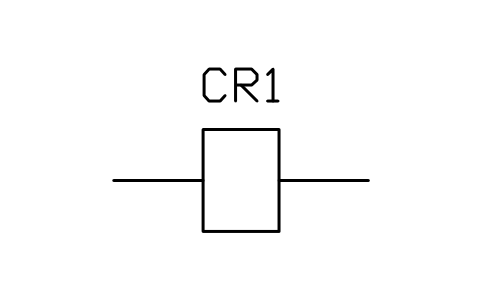 Operating coil, rectangle
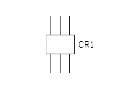
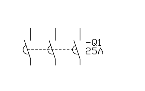 Contactor, 3-pole
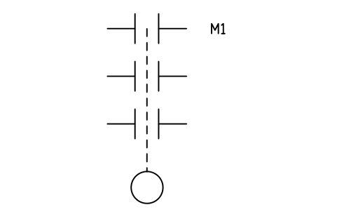 Contactor, three poles with operating coil
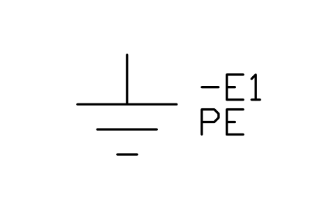
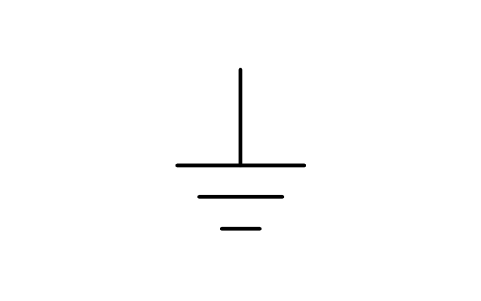
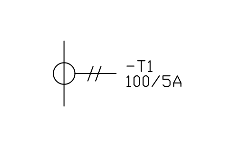
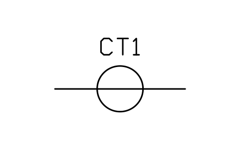
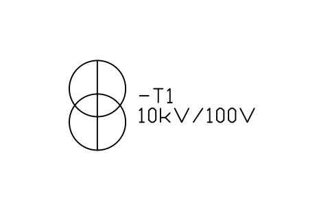
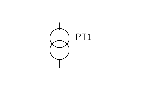
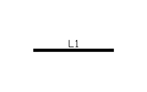
Fuses, breakers, earth and instrument transformers
IEC 60617
ANSI/IEEE 315
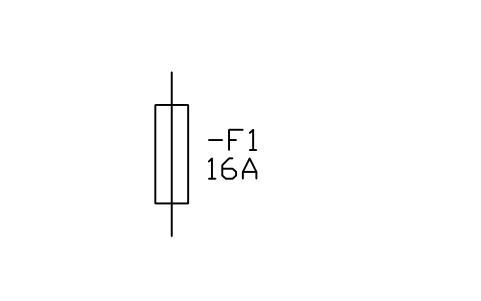
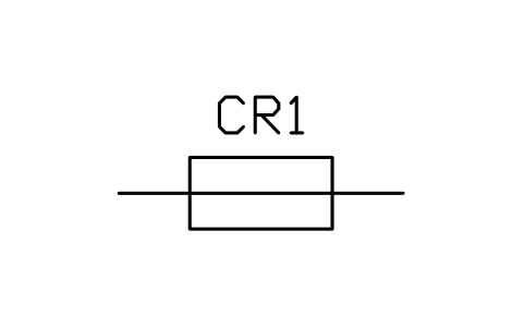
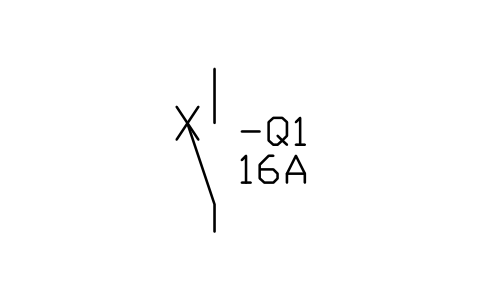
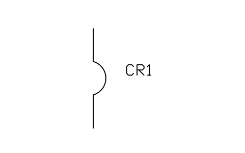
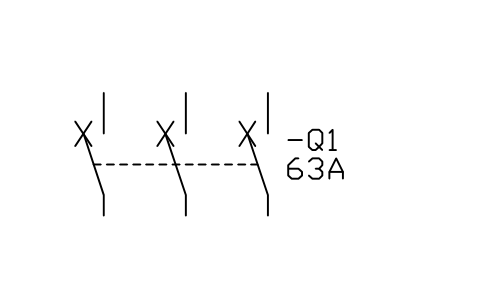
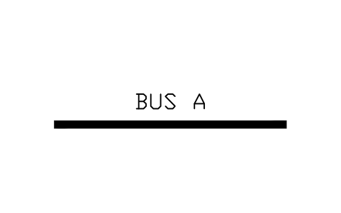
Meters and lamps
IEC 60617
ANSI/IEEE 315
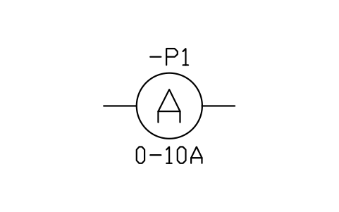
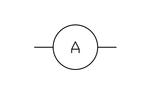
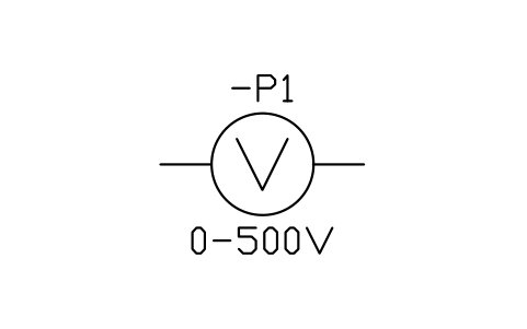
What differs most
- Resistor: IEC draws a rectangle, ANSI a zigzag. ANSI/IEEE 315 also shows the rectangle, so a rectangle is understood on both sides.
- Contacts: IEC draws a contact as a switch blade and numbers its terminals (13-14 for a make contact, 21-22 for a break contact). ANSI draws two short parallel bars, with a diagonal bar for a normally closed contact.
- Breakers and switches: IEC marks a circuit breaker with a cross on the switch blade. ANSI uses the box or half-circle forms of the power circuit breaker.
- Machines: IEC puts more inside the circle, such as 3~ for three-phase or GS for a synchronous generator. The ANSI forms are often just the letter M or G.
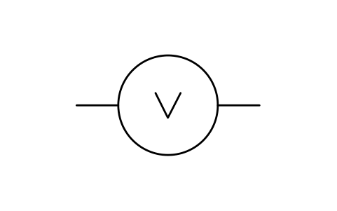
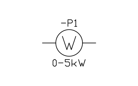
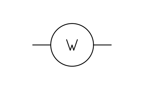
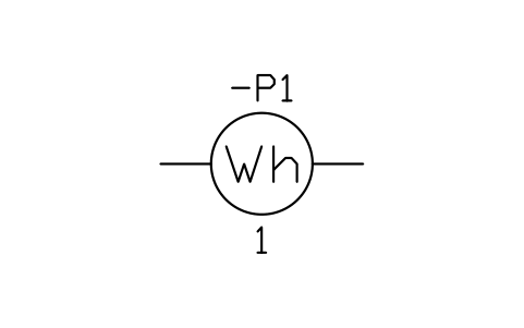
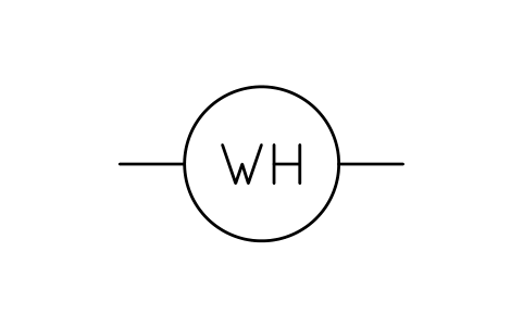
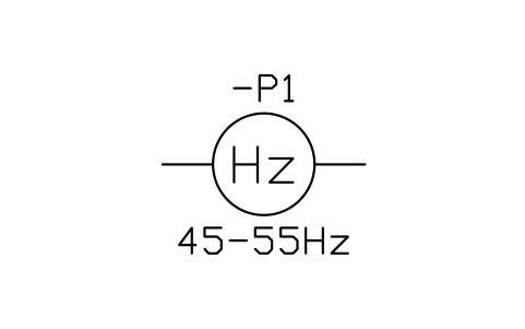
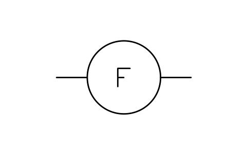
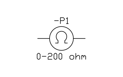
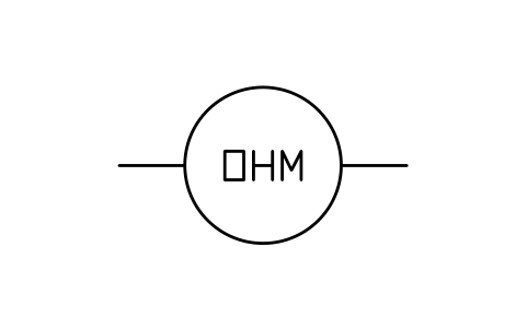
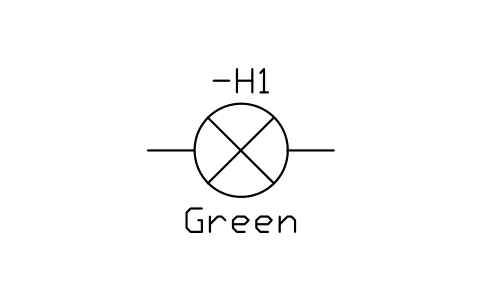
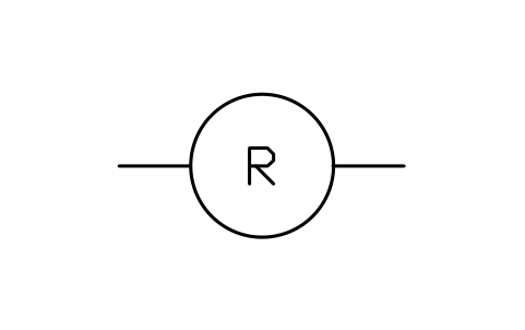
- Meters: both use a circle with a letter, but a few letters differ, for example Hz against F for frequency, Wh against WH, and the omega sign against OHM.
- Tags and layout: IEC drawings usually tag devices with letters such as K for relays and contactors, Q for breakers and F for protection. ANSI drawings often use CR, M or CB. Control circuits are often drawn as vertical current paths in IEC and as horizontal ladder rungs in ANSI.
Get both sets as DWG blocks
Both libraries are free and ready for AutoCAD, with attributes for tags and ratings. The motor control sample is drawn with the IEC forms and shows them in use.
Common questions
- Is ANSI/IEEE 315 still a valid standard?
- IEEE lists the 1975 edition (ANSI Y32.2, CSA Z99) as inactive. It was last reaffirmed in 1993, and a 1986 supplement added the internationally approved IEC symbols. Many North American drawings still follow it, so in practice your customer's drawing standard decides.
- Can I mix IEC and ANSI symbols in one drawing?
- Avoid it. One drawing should use one set, so the electricians who read it do not have to switch conventions. If a project forces a mix, for example with imported equipment, show both forms in the legend.
- Are your symbols certified copies of the standards?
- No. They are our own drawings after the common forms of the two standards. Check them against the legend of your project before you issue drawings.