
KaynaklarTek hat şeması sembolleri
Substation single-line diagram: sample DWGs and electrical template
Complete single-line diagrams of a substation on an ISO A3 sheet, drawn two ways: a 10/0.4 kV substation with a single busbar, and a 10 kV double busbar switchboard with two sections, a bus coupler and two incomers. Each has a protection schedule, a legend and a filled-in title block. All symbols are blocks from the power system single-line symbol library, with tags and ratings filled in.
Free to use and modify in your own projects, including commercial ones. The ZIP holds the sample drawing, a template, a plot style table and a README; no add-in needed. The data in the drawing is made up, so it is not for design or construction. Provided as is, without warranty.
Single busbar
One 10 kV busbar feeding two 1.6 MVA transformers and a voltage transformer, with a 0.4 kV board in two sections joined by a bus coupler and eight feeders.
Double busbar
A 10 kV switchboard with two busbars, each split into section I and section II by a section breaker. Two incomers, a bus coupler between the busbars, every bay on both busbars through two disconnectors, and four outgoing bays.
This sample uses these resources
The symbols are blocks from our own libraries, with their attributes filled in. The sheet and its title block come from our ISO A3 title block template. Download them to draw your own diagrams.
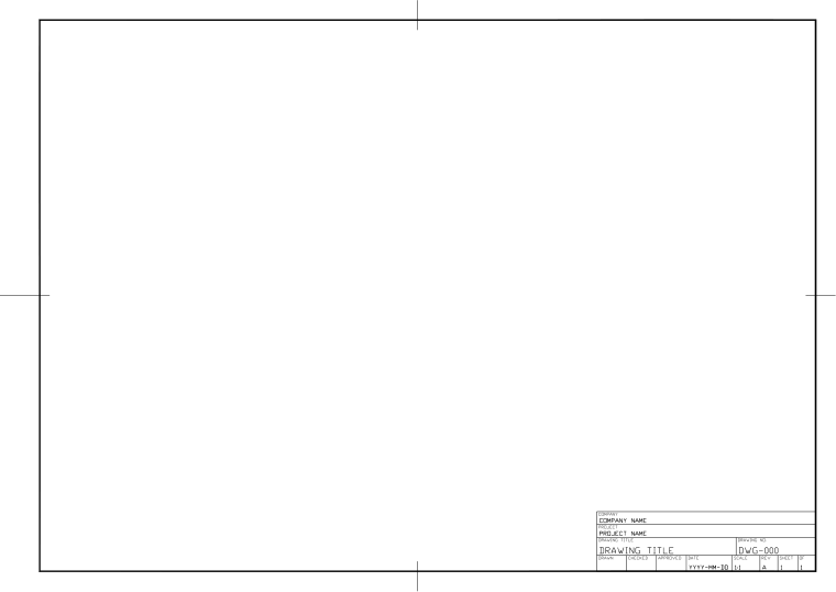
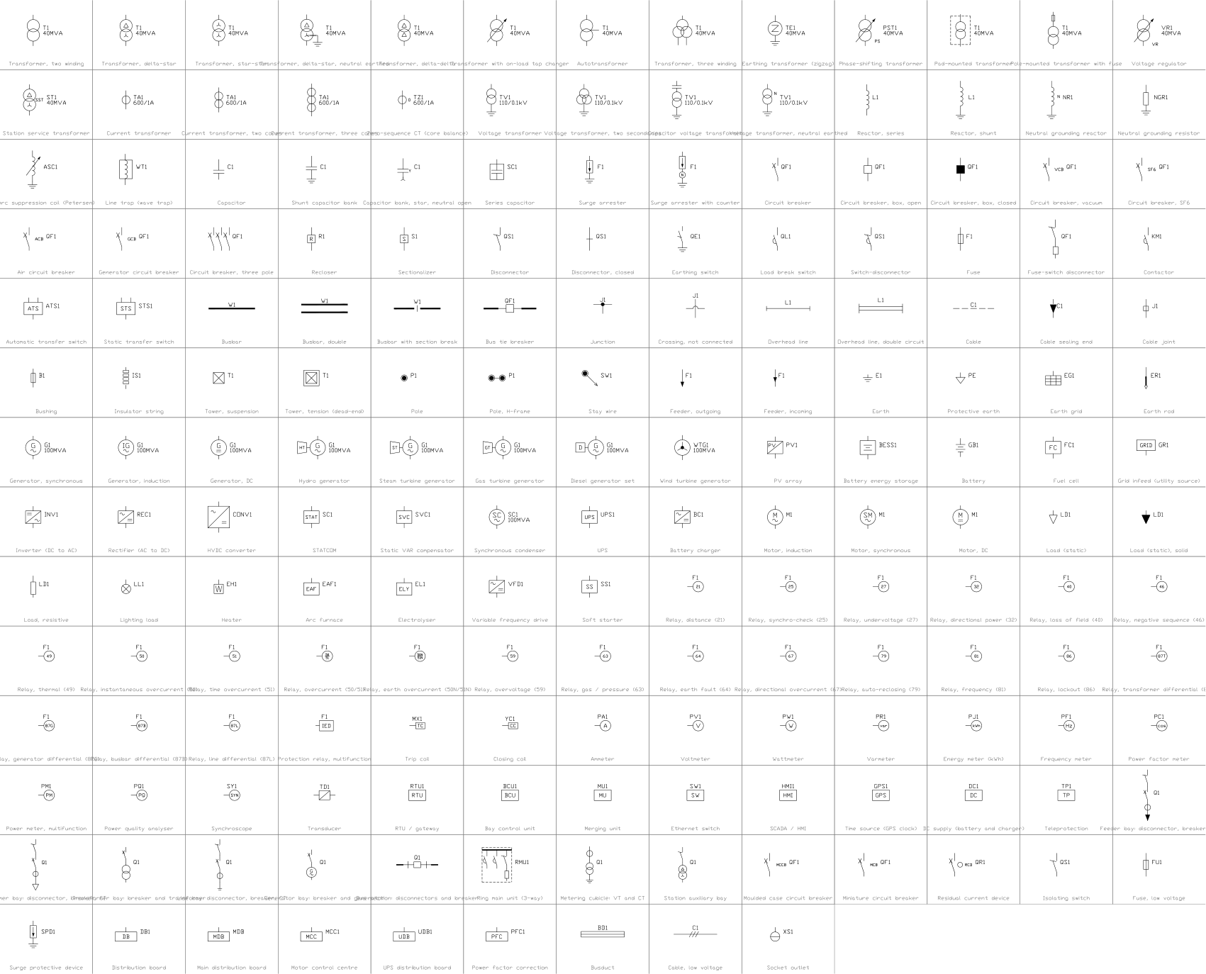
What is in the ZIP
- Substation-Single-Busbar-Sample.dwg
Sample drawing (DWG, AutoCAD 2018 format) - Substation-Double-Busbar-Sample.dwg
Sample drawing (DWG, AutoCAD 2018 format) - Electrical-Template-ISO-A3.dwt
Template (DWT) that the drawing was made on - CADXChange-Monochrome.ctb
Plot style table (CTB) that prints every colour black - README.txt
README with the layer list and how to use the files
Every ZIP holds its own drawing together with the template, the plot style table and the README.
The template
The electrical template has 16 layers with colours, line weights and linetypes (power circuits, busbars, control, signal, protective earth, enclosure boundaries, text and more), the text styles ISO-2.5 to ISO-5, the dimension style ISO-25 and an ISO A3 layout with a title block and revision table. The layer names are a common convention, not a standard; rename them to match your company's rules.
Layers defined
Every layer in the template with its colour, line weight and linetype, and how many objects of this sample are on it. Layers the sample does not use are still defined, ready for your own drawing.
| Layer | Colour | Line weight | Linetype | Used for | Single busbar | Double busbar |
|---|---|---|---|---|---|---|
| Electrical layers | ||||||
| ELEC-POWER | 1 | 0.50 mm | Continuous | Main power circuits | 37 | 64 |
| ELEC-BUS | 1 | 0.70 mm | Continuous | Busbars and heavy lines | 4 | 5 |
| ELEC-CONTROL | 4 | 0.25 mm | Continuous | Control circuits | not used here | not used here |
| ELEC-SIGNAL | 3 | 0.18 mm | Continuous | Signal, instrumentation and communication circuits | not used here | not used here |
| ELEC-PE | 2 | 0.35 mm | Continuous | Protective earth and bonding | not used here | not used here |
| ELEC-CABLE | 30 | 0.25 mm | DASHED | Cable, conduit and tray routes | not used here | not used here |
| SYMBOL | 7 | 0.25 mm | Continuous | Symbols (the layer the symbol libraries use) | 35 | 40 |
| ELEC-TERMINAL | 7 | 0.25 mm | Continuous | Terminals and connection points | not used here | not used here |
| ELEC-BOUNDARY | 5 | 0.18 mm | DASHDOT | Enclosure, panel and device boundaries | 2 | not used here |
| ELEC-MECH-LINK | 8 | 0.18 mm | DASHED | Mechanical links, interlocks and measuring links | 4 | 3 |
| ELEC-REF | 7 | 0.18 mm | Continuous | Reference designations (-QF1, -K2) | not used here | not used here |
| ELEC-WIRE-NO | 7 | 0.18 mm | Continuous | Wire numbers and cable labels | 8 | not used here |
| ELEC-XREF | 9 | 0.13 mm | Continuous | Contact and cross reference texts | not used here | not used here |
| ELEC-TEXT | 7 | 0.18 mm | Continuous | General text | 41 | 31 |
| ELEC-NOTES | 7 | 0.18 mm | Continuous | Notes and legends | 4 | 4 |
| ELEC-DIM | 3 | 0.18 mm | Continuous | Dimensions | not used here | not used here |
| Sheet and symbol layers | ||||||
| 0 | 7 | default | Continuous | Default layer, keep it empty | not used here | not used here |
| FRAME | 7 | default | Continuous | Sheet border | 5 | 5 |
| TITLEBLOCK | 7 | default | Continuous | Title block and revision table | 1 | 1 |
| VIEWPORT | 8 | default | Continuous | Layout viewport frame (does not plot) | 2 | 2 |
| DRAWING-AREA | 8 | default | Continuous | Boundary of the model drawing area (does not plot) | 2 | 2 |
Styles defined
The text styles, the dimension style and the linetypes that the template defines, so you do not have to set them up in each new drawing.
| Kind | Name | Settings |
|---|---|---|
| Text style | ISO | isocp.shx, 15°, variable height |
| Text style | ISO-2.5 | isocp.shx, 15°, 2.5 mm high |
| Text style | ISO-3.5 | isocp.shx, 15°, 3.5 mm high |
| Text style | ISO-5 | isocp.shx, 15°, 5 mm high |
| Text style | TB-en | Arial, used by the title block |
| Dimension style | ISO-25 | Text 2.5 mm, arrows 2.5 mm, extension lines 1.25 mm beyond the dimension line and 0.625 mm from the object, dimension lines 3.75 mm apart, 0 decimals |
| Linetype | Continuous | Solid line |
| Linetype | DASHED | Dashed |
| Linetype | DASHDOT | Dash-dot |
| Linetype | CENTER | Centre line |
| Linetype | PHANTOM | Phantom line |
| Linetype | HIDDEN | Hidden line |
Sheet and drawing setup
How the sheet is set up, so your own drawings print the same way.
- Sheet
- ISO A3 landscape, 420 × 297 mm.
- Layout
- One layout named ISO-A3, plotted at 1:1 on full-bleed A3 media, so the sheet has no printer margin.
- Border
- 20 mm from the left edge (binding side) and 10 mm from the other edges; the drawing area inside is 390 × 277 mm.
- Model space
- Units are millimetres. The drawing area is shown at 1:1, so 1 mm in the drawing is 1 mm on paper.
- Title block
- 160 × 79 mm at the lower right, with a four-line revision table above the company, project, title and approval fields.
- Text size
- 2.5 mm for labels and notes, 3.5 mm and 5 mm for headings.
- Linetype scale
- 1, so dashes are sized for plotting at 1:1.
- Plot style
- None set. Pick the CTB from the ZIP in the page setup for black-and-white plots.
Single busbar
Title block fields
The attributes of the title block. Double-click it to fill them in, or write them for a whole set of drawings with BlockSync.
| Attribute | Field on the sheet | Value in this sample |
|---|---|---|
| COMPANY | COMPANY | CADXChange |
| PROJECT | PROJECT | 10/0.4 kV Distribution Substation |
| AREA | AREA | Substation |
| SYSTEM | SYSTEM | 10 kV / 0.4 kV |
| CLIENT | CLIENT | Sample |
| TITLE | DRAWING TITLE | Single-line diagram |
| DRAWING_NO | DRAWING NO. | E-001 |
| CONTRACT_NO | CONTRACT NO. | — |
| REV | REV | A |
| DRAWN | DRAWN | — |
| CHECKED | CHECKED | — |
| APPROVED | APPROVED | — |
| DATE | DATE | 2026-10-20 |
| SCALE | SCALE | NTS |
| SHEET | SHEET | 1 |
| SHEET_OF | OF | 1 |
Revision table: R1 to R4, each with REV, DATE, DESCRIPTION and BY (16 attributes, empty in this sample).
Blocks in the drawing
The equipment list of the drawing: block name, symbol and how many times it is placed. BlockSync exports the same list from your own drawings.
| Symbol | Block | Placed |
|---|---|---|
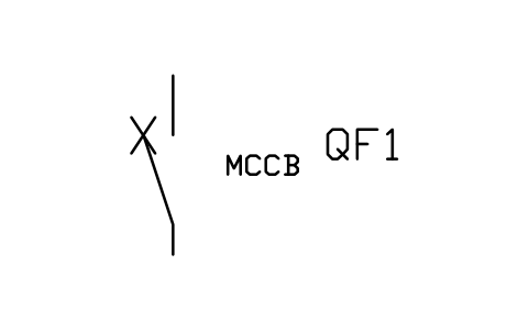 Moulded case circuit breaker | PWR_LV_MCCB | 8 |
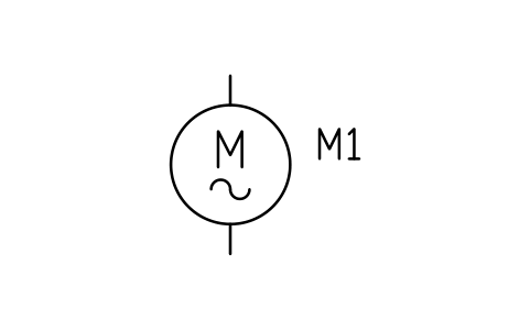 Motor, induction | PWR_MOTOR_IM | 4 |
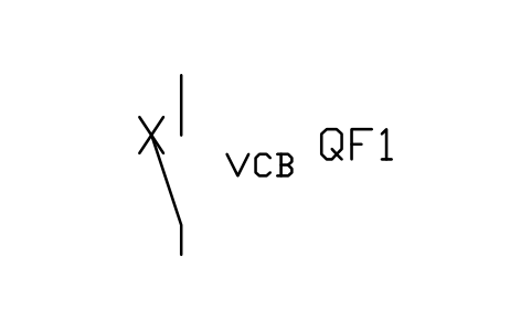 Circuit breaker, vacuum | PWR_CB_VCB | 3 |
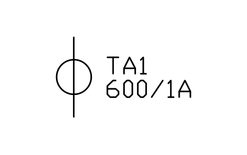 Current transformer | PWR_CT | 3 |
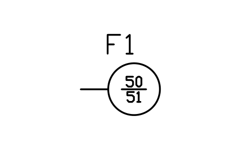 Relay, overcurrent (50/51) | PWR_R_5051 | 3 |
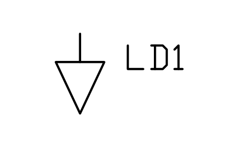 Load (static) | PWR_LOAD | 3 |
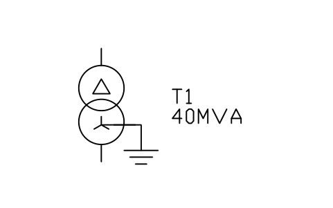 Transformer, delta-star, neutral earthed | PWR_TX_DYN | 2 |
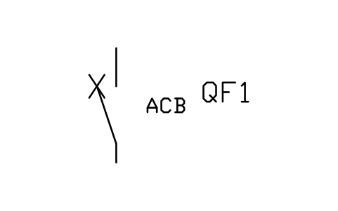 Air circuit breaker | PWR_CB_ACB | 2 |
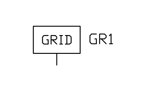 Grid infeed (utility source) | PWR_GRID | 1 |
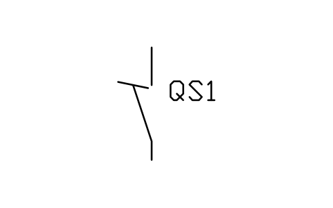 Disconnector | PWR_DISCONNECTOR | 1 |
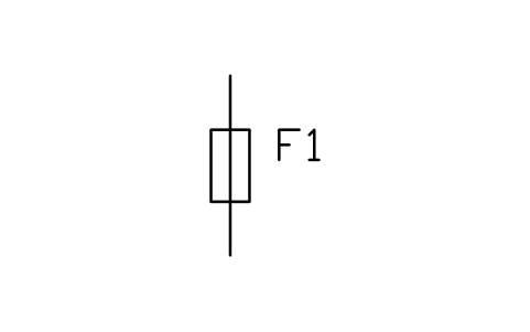 Fuse | PWR_FUSE | 1 |
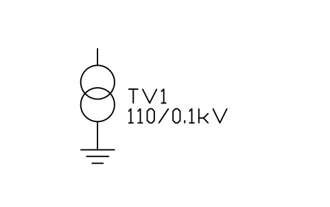 Voltage transformer | PWR_VT | 1 |
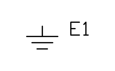 Earth | PWR_EARTH | 1 |
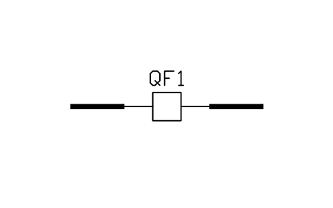 Bus tie breaker | PWR_BUS_TIE | 1 |
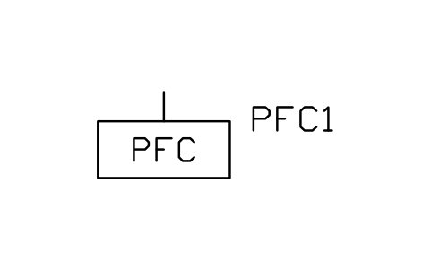 Power factor correction | PWR_LV_PFC | 1 |
Equipment schedule
One row per placed symbol, read from the attributes of the blocks in the drawing: what is shown on the sheet, and the schedule attributes that were filled in but are not shown. BlockSync exports these same attributes from your own drawings.
| Tag | Description | Shown on the sheet | Filled in, not shown |
|---|---|---|---|
| G1 | Grid infeed (utility source)PWR_GRID | RATING = 250 MVA | VOLTAGE_KV = 10 |
| QS1 | DisconnectorPWR_DISCONNECTOR | RATED_KV = 12 kV | RATED_CURRENT_A = 630SHORT_TIME_KA = 25EARTHING_SWITCH = NoMECHANISM = Manual |
| QF1 | Circuit breaker, vacuumPWR_CB_VCB | RATED_KV = 12 kV | RATED_CURRENT_A = 630BREAKING_KA = 25INTERRUPTER = VacuumMECHANISM = SpringCONTROL_VOLTAGE = 110 V DC |
| TA1 | Current transformerPWR_CT | RATIO = 200/1 A | CLASS = 5P20BURDEN_VA = 15CORES = 2RATED_KV = 12 |
| F1 | Relay, overcurrent (50/51)PWR_R_5051 | FUNCTION = OC / EF | SETTING = I> 1.2 In, 0.3 s; I>> 8 In, 0.1 sTRIPS = QF1CT_INPUT = TA1 |
| QF2 | Circuit breaker, vacuumPWR_CB_VCB | RATED_KV = 12 kV | RATED_CURRENT_A = 630BREAKING_KA = 25INTERRUPTER = VacuumMECHANISM = SpringCONTROL_VOLTAGE = 110 V DC |
| TA2 | Current transformerPWR_CT | RATIO = 100/1 A | CLASS = 5P20BURDEN_VA = 15CORES = 2RATED_KV = 12 |
| T1 | Transformer, delta-star, neutral earthedPWR_TX_DYN | RATING_MVA = 1.6 MVA | VOLTAGE_RATIO = 10/0.4 kVVECTOR_GROUP = Dyn11IMPEDANCE_PCT = 6TAP_RANGE = +/-2x2.5%COOLING = ONANNEUTRAL_EARTHING = Solid |
| QF4 | Air circuit breakerPWR_CB_ACB | RATED_KV = 0.69 kV | RATED_CURRENT_A = 2500BREAKING_KA = 50INTERRUPTER = AirMECHANISM = Motor-charged springCONTROL_VOLTAGE = 110 V DC |
| F2 | Relay, overcurrent (50/51)PWR_R_5051 | FUNCTION = OC / EF | SETTING = I> 1.1 In, 0.4 s; I>> 7 In, 0.1 sTRIPS = QF2CT_INPUT = TA2 |
| QF3 | Circuit breaker, vacuumPWR_CB_VCB | RATED_KV = 12 kV | RATED_CURRENT_A = 630BREAKING_KA = 25INTERRUPTER = VacuumMECHANISM = SpringCONTROL_VOLTAGE = 110 V DC |
| TA3 | Current transformerPWR_CT | RATIO = 100/1 A | CLASS = 5P20BURDEN_VA = 15CORES = 2RATED_KV = 12 |
| T2 | Transformer, delta-star, neutral earthedPWR_TX_DYN | RATING_MVA = 1.6 MVA | VOLTAGE_RATIO = 10/0.4 kVVECTOR_GROUP = Dyn11IMPEDANCE_PCT = 6TAP_RANGE = +/-2x2.5%COOLING = ONANNEUTRAL_EARTHING = Solid |
| QF5 | Air circuit breakerPWR_CB_ACB | RATED_KV = 0.69 kV | RATED_CURRENT_A = 2500BREAKING_KA = 50INTERRUPTER = AirMECHANISM = Motor-charged springCONTROL_VOLTAGE = 110 V DC |
| F3 | Relay, overcurrent (50/51)PWR_R_5051 | FUNCTION = OC / EF | SETTING = I> 1.1 In, 0.4 s; I>> 7 In, 0.1 sTRIPS = QF3CT_INPUT = TA3 |
| FU1 | FusePWR_FUSE | RATED_KV = 12 kV | RATED_CURRENT_A = 6BREAKING_KA = 50CHARACTERISTIC = Current limiting |
| TV1 | Voltage transformerPWR_VT | RATIO = 10/0.1 kV | CLASS = 0.5BURDEN_VA = 50WINDINGS = 2RATED_KV = 12 |
| E1 | EarthPWR_EARTH | EARTH_TYPE = PE | |
| QF6 | Bus tie breakerPWR_BUS_TIE | VOLTAGE_KV = 0.4 | RATED_CURRENT_A = 2000CONDUCTOR = Copper busbarSHORT_CIRCUIT_KA = 50 |
| QM11 | Moulded case circuit breakerPWR_LV_MCCB | RATED_CURRENT_A = 125 A | VOLTAGE = 400 VBREAKING_KA = 36TRIP_UNIT = Thermal-magneticPOLES = 3 |
| M1 | Motor, inductionPWR_MOTOR_IM | POWER_KW = 30 kW | VOLTAGE = 400 VPOWER_FACTOR = 0.85STARTING = Star-deltaSERVICE = Feed pump P-101 |
| QM12 | Moulded case circuit breakerPWR_LV_MCCB | RATED_CURRENT_A = 125 A | VOLTAGE = 400 VBREAKING_KA = 36TRIP_UNIT = Thermal-magneticPOLES = 3 |
| M2 | Motor, inductionPWR_MOTOR_IM | POWER_KW = 75 kW | VOLTAGE = 400 VPOWER_FACTOR = 0.85STARTING = Star-deltaSERVICE = Cooling fan F-201 |
| QM13 | Moulded case circuit breakerPWR_LV_MCCB | RATED_CURRENT_A = 125 A | VOLTAGE = 400 VBREAKING_KA = 36TRIP_UNIT = Thermal-magneticPOLES = 3 |
| L1 | Load (static)PWR_LOAD | POWER_KW = 20 kW | VOLTAGE = 400 VPOWER_FACTOR = 0.95SERVICE = Lighting LP-1 |
| QM14 | Moulded case circuit breakerPWR_LV_MCCB | RATED_CURRENT_A = 125 A | VOLTAGE = 400 VBREAKING_KA = 36TRIP_UNIT = Thermal-magneticPOLES = 3 |
| C1 | Power factor correctionPWR_LV_PFC | RATED_CURRENT_A = 100 kvar | VOLTAGE = 400 VBREAKING_KA = 36TRIP_UNIT = Thermal-magneticPOLES = 3 |
| QM15 | Moulded case circuit breakerPWR_LV_MCCB | RATED_CURRENT_A = 125 A | VOLTAGE = 400 VBREAKING_KA = 36TRIP_UNIT = Thermal-magneticPOLES = 3 |
| M3 | Motor, inductionPWR_MOTOR_IM | POWER_KW = 55 kW | VOLTAGE = 400 VPOWER_FACTOR = 0.85STARTING = Star-deltaSERVICE = Compressor K-301 |
| QM16 | Moulded case circuit breakerPWR_LV_MCCB | RATED_CURRENT_A = 125 A | VOLTAGE = 400 VBREAKING_KA = 36TRIP_UNIT = Thermal-magneticPOLES = 3 |
| L2 | Load (static)PWR_LOAD | POWER_KW = 40 kW | VOLTAGE = 400 VPOWER_FACTOR = 0.95SERVICE = Heating HP-1 |
| QM17 | Moulded case circuit breakerPWR_LV_MCCB | RATED_CURRENT_A = 125 A | VOLTAGE = 400 VBREAKING_KA = 36TRIP_UNIT = Thermal-magneticPOLES = 3 |
| L3 | Load (static)PWR_LOAD | POWER_KW = 60 kW | VOLTAGE = 400 VPOWER_FACTOR = 0.95SERVICE = Process PP-1 |
| QM18 | Moulded case circuit breakerPWR_LV_MCCB | RATED_CURRENT_A = 125 A | VOLTAGE = 400 VBREAKING_KA = 36TRIP_UNIT = Thermal-magneticPOLES = 3 |
| M4 | Motor, inductionPWR_MOTOR_IM | POWER_KW = 37 kW | VOLTAGE = 400 VPOWER_FACTOR = 0.85STARTING = Star-deltaSERVICE = Mixer A-401 |
Manufacturer, model and remarks are left empty on every block, ready for your data. The values are examples.
Double busbar
Title block fields
The attributes of the title block. Double-click it to fill them in, or write them for a whole set of drawings with BlockSync.
| Attribute | Field on the sheet | Value in this sample |
|---|---|---|
| COMPANY | COMPANY | CADXChange |
| PROJECT | PROJECT | 10/0.4 kV Distribution Substation |
| AREA | AREA | Substation |
| SYSTEM | SYSTEM | 10 kV |
| CLIENT | CLIENT | Sample |
| TITLE | DRAWING TITLE | Single-line diagram, double busbar |
| DRAWING_NO | DRAWING NO. | E-002 |
| CONTRACT_NO | CONTRACT NO. | — |
| REV | REV | A |
| DRAWN | DRAWN | — |
| CHECKED | CHECKED | — |
| APPROVED | APPROVED | — |
| DATE | DATE | 2026-10-20 |
| SCALE | SCALE | NTS |
| SHEET | SHEET | 1 |
| SHEET_OF | OF | 1 |
Revision table: R1 to R4, each with REV, DATE, DESCRIPTION and BY (16 attributes, empty in this sample).
Blocks in the drawing
The equipment list of the drawing: block name, symbol and how many times it is placed. BlockSync exports the same list from your own drawings.
| Symbol | Block | Placed |
|---|---|---|
| Disconnector | PWR_DISCONNECTOR | 14 |
| Circuit breaker, vacuum | PWR_CB_VCB | 9 |
| Current transformer | PWR_CT | 6 |
| Grid infeed (utility source) | PWR_GRID | 2 |
| Relay, overcurrent (50/51) | PWR_R_5051 | 2 |
| Transformer, delta-star, neutral earthed | PWR_TX_DYN | 2 |
| Fuse | PWR_FUSE | 1 |
| Voltage transformer | PWR_VT | 1 |
| Earth | PWR_EARTH | 1 |
| Motor, induction | PWR_MOTOR_IM | 1 |
| Load (static) | PWR_LOAD | 1 |
Equipment schedule
One row per placed symbol, read from the attributes of the blocks in the drawing: what is shown on the sheet, and the schedule attributes that were filled in but are not shown. BlockSync exports these same attributes from your own drawings.
| Tag | Description | Shown on the sheet | Filled in, not shown |
|---|---|---|---|
| QF4 | Circuit breaker, vacuumPWR_CB_VCB | RATED_KV = 12 kV | RATED_CURRENT_A = 630BREAKING_KA = 25INTERRUPTER = VacuumMECHANISM = SpringCONTROL_VOLTAGE = 110 V DC |
| QF5 | Circuit breaker, vacuumPWR_CB_VCB | RATED_KV = 12 kV | RATED_CURRENT_A = 630BREAKING_KA = 25INTERRUPTER = VacuumMECHANISM = SpringCONTROL_VOLTAGE = 110 V DC |
| G1 | Grid infeed (utility source)PWR_GRID | RATING = 250 MVA | VOLTAGE_KV = 10 |
| QF1 | Circuit breaker, vacuumPWR_CB_VCB | RATED_KV = 12 kV | RATED_CURRENT_A = 630BREAKING_KA = 25INTERRUPTER = VacuumMECHANISM = SpringCONTROL_VOLTAGE = 110 V DC |
| TA1 | Current transformerPWR_CT | RATIO = 400/1 A | CLASS = 5P20BURDEN_VA = 15CORES = 2RATED_KV = 12 |
| QS11 | DisconnectorPWR_DISCONNECTOR | RATED_CURRENT_A = 630SHORT_TIME_KA = 25EARTHING_SWITCH = NoMECHANISM = Manual | |
| QS12 | DisconnectorPWR_DISCONNECTOR | RATED_CURRENT_A = 630SHORT_TIME_KA = 25EARTHING_SWITCH = NoMECHANISM = Manual | |
| F1 | Relay, overcurrent (50/51)PWR_R_5051 | FUNCTION = OC / EF | SETTING = I> 1.2 In, 0.3 s; I>> 8 In, 0.1 sTRIPS = QF1CT_INPUT = TA1 |
| G2 | Grid infeed (utility source)PWR_GRID | RATING = 250 MVA | VOLTAGE_KV = 10 |
| QF2 | Circuit breaker, vacuumPWR_CB_VCB | RATED_KV = 12 kV | RATED_CURRENT_A = 630BREAKING_KA = 25INTERRUPTER = VacuumMECHANISM = SpringCONTROL_VOLTAGE = 110 V DC |
| TA2 | Current transformerPWR_CT | RATIO = 400/1 A | CLASS = 5P20BURDEN_VA = 15CORES = 2RATED_KV = 12 |
| QS21 | DisconnectorPWR_DISCONNECTOR | RATED_CURRENT_A = 630SHORT_TIME_KA = 25EARTHING_SWITCH = NoMECHANISM = Manual | |
| QS22 | DisconnectorPWR_DISCONNECTOR | RATED_CURRENT_A = 630SHORT_TIME_KA = 25EARTHING_SWITCH = NoMECHANISM = Manual | |
| F2 | Relay, overcurrent (50/51)PWR_R_5051 | FUNCTION = OC / EF | SETTING = I> 1.2 In, 0.3 s; I>> 8 In, 0.1 sTRIPS = QF2CT_INPUT = TA2 |
| QS31 | DisconnectorPWR_DISCONNECTOR | RATED_KV = 12 kV | RATED_CURRENT_A = 630SHORT_TIME_KA = 25EARTHING_SWITCH = NoMECHANISM = Manual |
| QF3 | Circuit breaker, vacuumPWR_CB_VCB | RATED_KV = 12 kV | RATED_CURRENT_A = 630BREAKING_KA = 25INTERRUPTER = VacuumMECHANISM = SpringCONTROL_VOLTAGE = 110 V DC |
| QS32 | DisconnectorPWR_DISCONNECTOR | RATED_KV = 12 kV | RATED_CURRENT_A = 630SHORT_TIME_KA = 25EARTHING_SWITCH = NoMECHANISM = Manual |
| FU1 | FusePWR_FUSE | RATED_KV = 12 kV | RATED_CURRENT_A = 6BREAKING_KA = 50CHARACTERISTIC = Current limiting |
| TV1 | Voltage transformerPWR_VT | RATIO = 10/0.1 kV | CLASS = 0.5BURDEN_VA = 50WINDINGS = 2RATED_KV = 12 |
| E1 | EarthPWR_EARTH | EARTH_TYPE = PE | |
| QS101 | DisconnectorPWR_DISCONNECTOR | RATED_CURRENT_A = 630SHORT_TIME_KA = 25EARTHING_SWITCH = NoMECHANISM = Manual | |
| QS102 | DisconnectorPWR_DISCONNECTOR | RATED_CURRENT_A = 630SHORT_TIME_KA = 25EARTHING_SWITCH = NoMECHANISM = Manual | |
| QF10 | Circuit breaker, vacuumPWR_CB_VCB | RATED_KV = 12 kV | RATED_CURRENT_A = 630BREAKING_KA = 25INTERRUPTER = VacuumMECHANISM = SpringCONTROL_VOLTAGE = 110 V DC |
| TA10 | Current transformerPWR_CT | RATIO = 200/1 A | CLASS = 5P20BURDEN_VA = 15CORES = 2RATED_KV = 12 |
| T1 | Transformer, delta-star, neutral earthedPWR_TX_DYN | RATING_MVA = 1.6 MVA | VOLTAGE_RATIO = 10/0.4 kVVECTOR_GROUP = Dyn11IMPEDANCE_PCT = 6TAP_RANGE = +/-2x2.5%COOLING = ONANNEUTRAL_EARTHING = Solid |
| QS111 | DisconnectorPWR_DISCONNECTOR | RATED_CURRENT_A = 630SHORT_TIME_KA = 25EARTHING_SWITCH = NoMECHANISM = Manual | |
| QS112 | DisconnectorPWR_DISCONNECTOR | RATED_CURRENT_A = 630SHORT_TIME_KA = 25EARTHING_SWITCH = NoMECHANISM = Manual | |
| QF11 | Circuit breaker, vacuumPWR_CB_VCB | RATED_KV = 12 kV | RATED_CURRENT_A = 630BREAKING_KA = 25INTERRUPTER = VacuumMECHANISM = SpringCONTROL_VOLTAGE = 110 V DC |
| TA11 | Current transformerPWR_CT | RATIO = 200/1 A | CLASS = 5P20BURDEN_VA = 15CORES = 2RATED_KV = 12 |
| T2 | Transformer, delta-star, neutral earthedPWR_TX_DYN | RATING_MVA = 1.6 MVA | VOLTAGE_RATIO = 10/0.4 kVVECTOR_GROUP = Dyn11IMPEDANCE_PCT = 6TAP_RANGE = +/-2x2.5%COOLING = ONANNEUTRAL_EARTHING = Solid |
| QS121 | DisconnectorPWR_DISCONNECTOR | RATED_CURRENT_A = 630SHORT_TIME_KA = 25EARTHING_SWITCH = NoMECHANISM = Manual | |
| QS122 | DisconnectorPWR_DISCONNECTOR | RATED_CURRENT_A = 630SHORT_TIME_KA = 25EARTHING_SWITCH = NoMECHANISM = Manual | |
| QF12 | Circuit breaker, vacuumPWR_CB_VCB | RATED_KV = 12 kV | RATED_CURRENT_A = 630BREAKING_KA = 25INTERRUPTER = VacuumMECHANISM = SpringCONTROL_VOLTAGE = 110 V DC |
| TA12 | Current transformerPWR_CT | RATIO = 200/1 A | CLASS = 5P20BURDEN_VA = 15CORES = 2RATED_KV = 12 |
| M1 | Motor, inductionPWR_MOTOR_IM | POWER_KW = 800 kW | VOLTAGE = 10 kVPOWER_FACTOR = 0.85STARTING = Star-deltaSERVICE = Compressor K-101 |
| QS131 | DisconnectorPWR_DISCONNECTOR | RATED_CURRENT_A = 630SHORT_TIME_KA = 25EARTHING_SWITCH = NoMECHANISM = Manual | |
| QS132 | DisconnectorPWR_DISCONNECTOR | RATED_CURRENT_A = 630SHORT_TIME_KA = 25EARTHING_SWITCH = NoMECHANISM = Manual | |
| QF13 | Circuit breaker, vacuumPWR_CB_VCB | RATED_KV = 12 kV | RATED_CURRENT_A = 630BREAKING_KA = 25INTERRUPTER = VacuumMECHANISM = SpringCONTROL_VOLTAGE = 110 V DC |
| TA13 | Current transformerPWR_CT | RATIO = 200/1 A | CLASS = 5P20BURDEN_VA = 15CORES = 2RATED_KV = 12 |
| L1 | Load (static)PWR_LOAD | POWER_KW = 2500 kW | VOLTAGE = 10 kVPOWER_FACTOR = 0.95SERVICE = To substation SS-2 |
Manufacturer, model and remarks are left empty on every block, ready for your data. The values are examples.
How to use it
- Open the sample drawing to see how layers, text and the title block are used, or open it in the browser first, nothing to install.
- Start your own drawing from the template (NEW, then pick the DWT file). Copy the CTB file to your plot styles folder if you want black-and-white plots.
- Insert blocks from the symbol library into your drawing. The blocks in the sample are copies; they do not change when a library changes.
- Double-click the title block to fill it in, then export the equipment list with BlockSync.
Frequently asked questions
- Can I use the drawing for a real project?
- As a starting point for layout and layers, yes. The ratings, settings and cable sizes are made up, so the diagram has to be checked and changed for your project before it is used for design or construction.
- Why are the layers coloured?
- Colours and line weights follow the layers: power circuits are red and heavy, control is cyan, signal is green. The plot style table in the ZIP prints everything black and keeps the line weights, so you can plot in black and white as well.
- Which CAD programs open it?
- The drawing and the template are in AutoCAD 2018 format, which AutoCAD 2018 and later open, and so do other CAD programs that read this format. The browser viewer needs nothing installed.