
ResourcesElectrical schematic symbolsMotor control circuit diagram
Hoist drive with brake
A crane hoist drive: line contactor, converter drawn with its terminals, braking resistor and a motor with a holding brake. The control circuit has an emergency stop, up and down relays with limit switches and interlocks, and a brake coil released by a relay output of the drive.
Free to use and modify in your own projects, including commercial ones. The ZIP holds the sample drawing, a template, a plot style table and a README; no add-in needed. The data in the drawing is made up, so it is not for design or construction. Provided as is, without warranty. Library terms (CXL-1.0)
Version 1.0 · updated October 21, 2026
This sample uses these resources
The symbols are blocks from our own libraries, with their attributes filled in. The sheet and its title block come from our ISO A3 title block template. Download them to draw your own diagrams.
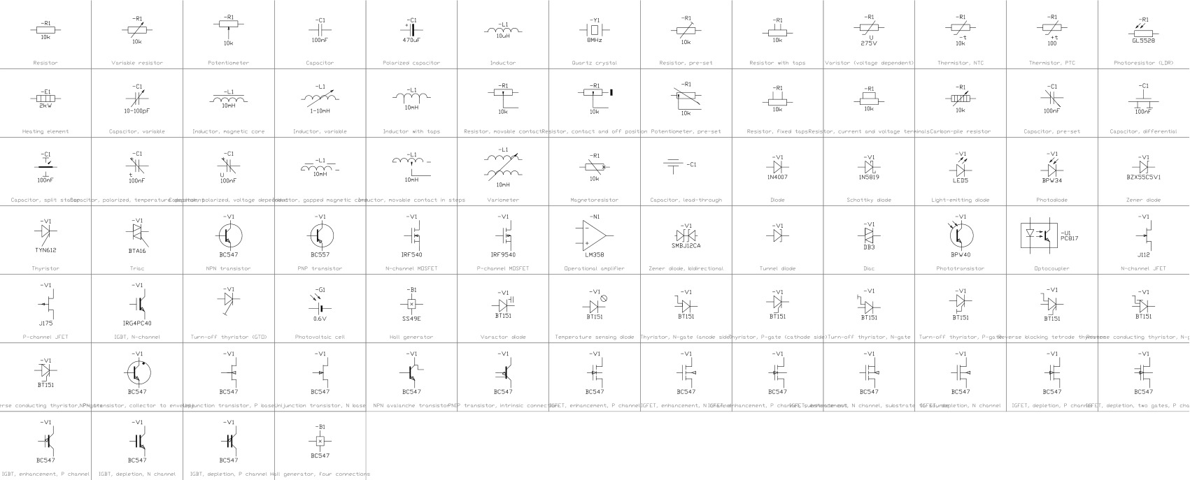
Layers, styles and sheet setup are the same for every drawing in the series; they are described on the series page: Motor control circuit diagram
Title block fields
The attributes of the title block. Double-click it to fill them in, or write them for a whole set of drawings with BlockSync.
| Attribute | Field on the sheet | Value in this sample |
|---|---|---|
| COMPANY | COMPANY | CADXChange |
| PROJECT | PROJECT | Workshop Crane Hoist |
| AREA | AREA | Workshop |
| SYSTEM | SYSTEM | 400 V / 230 V |
| CLIENT | CLIENT | Sample |
| TITLE | DRAWING TITLE | Hoist drive with brake |
| DRAWING_NO | DRAWING NO. | E-107 |
| CONTRACT_NO | CONTRACT NO. | — |
| REV | REV | A |
| DRAWN | DRAWN | — |
| CHECKED | CHECKED | — |
| APPROVED | APPROVED | — |
| DATE | DATE | 2026-10-22 |
| SCALE | SCALE | NTS |
| SHEET | SHEET | 1 |
| SHEET_OF | OF | 1 |
Revision table: R1 to R4, each with REV, DATE, DESCRIPTION and BY (16 attributes, empty in this sample).
Blocks in the drawing
The equipment list of the drawing: block name, symbol and how many times it is placed. BlockSync exports the same list from your own drawings.
| Symbol | Block | Placed |
|---|---|---|
 Junction | IEC_JUNCTION | 15 |
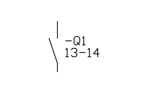 Auxiliary contact, NO | IEC_AUX_CONTACT_NO | 4 |
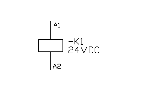 Relay / contactor coil | IEC_COIL | 4 |
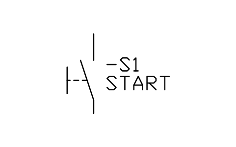 Push-button, NO | IEC_PUSHBUTTON_NO | 3 |
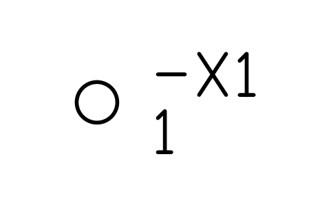 Terminal | IEC_TERMINAL | 2 |
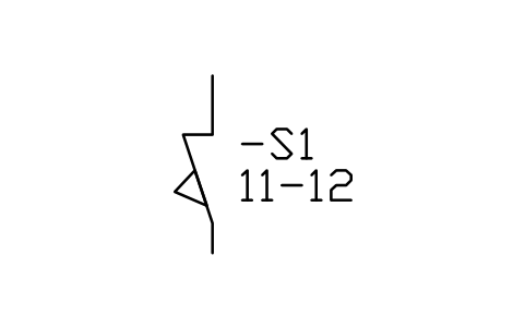 Limit switch, NC | IEC_LIMIT_NC | 2 |
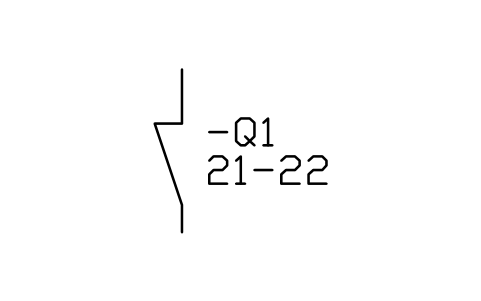 Auxiliary contact, NC | IEC_AUX_CONTACT_NC | 2 |
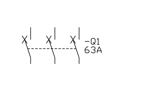 Circuit-breaker, 3-pole | IEC_CIRCUIT_BREAKER_3P | 1 |
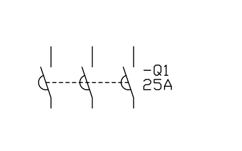 Contactor, 3-pole | IEC_CONTACTOR_3P | 1 |
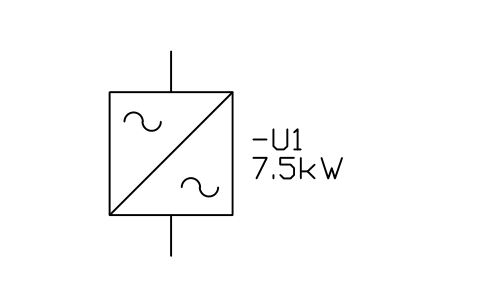 Frequency converter | IEC_FREQUENCY_CONVERTER | 1 |
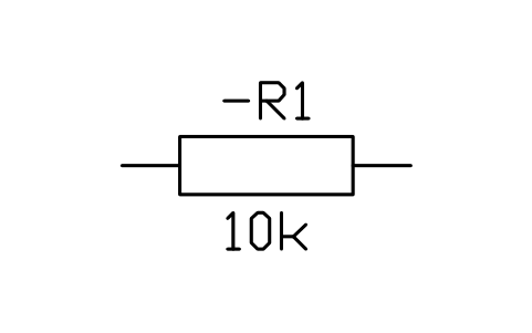 Resistor | IEC_RESISTOR | 1 |
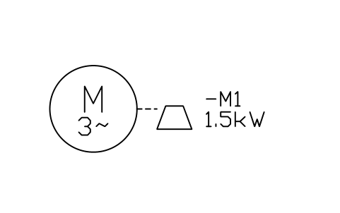 Motor with brake | IEC_MOTOR_BRAKE | 1 |
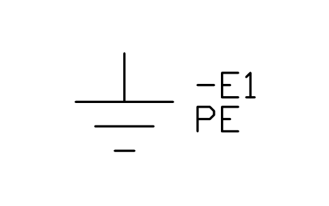 Earth (ground) | IEC_EARTH | 1 |
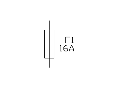 Fuse | IEC_FUSE | 1 |
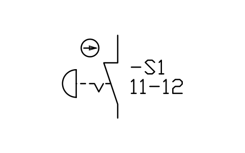 Emergency stop, NC | IEC_ESTOP | 1 |
Equipment schedule
One row per placed symbol, read from the attributes of the blocks in the drawing: what is shown on the sheet, and the schedule attributes that were filled in but are not shown. BlockSync exports these same attributes from your own drawings.
| Tag | Description | Shown on the sheet | Filled in, not shown |
|---|---|---|---|
| Q1 | Circuit-breaker, 3-poleIEC_CIRCUIT_BREAKER_3P | RATING_A = C40 | POLES = 3CURVE = CBREAKING_KA = 10VOLTAGE = 400 V |
| KM1 | Contactor, 3-poleIEC_CONTACTOR_3P | RATING_A = 32 A | POLES = 3UTILIZATION = AC-3COIL_VOLTAGE = 230 V AC |
| VFD1 | Frequency converterIEC_FREQUENCY_CONVERTER | POWER_KW = 11 kW | INPUT_V = 400 V 3~OUTPUT_HZ = 0-50 HzOUTPUT_A = 25 APROTECTION = IP21 |
| R1 | ResistorIEC_RESISTOR | VALUE = 22 ohm | POWER = 1500 WTOLERANCE = 5% |
| M1 | Motor with brakeIEC_MOTOR_BRAKE | POWER_KW = 11 kW | VOLTAGE = 400 VCURRENT = 22 ABRAKE_V = 230 V ACBRAKE_NM = 120 |
| PE1 | Earth (ground)IEC_EARTH | EARTH_TYPE = PE | |
| X2 | TerminalIEC_TERMINAL | TERMINAL_NO = 1 | |
| F2 | FuseIEC_FUSE | RATING_A = 6 A | VOLTAGE = 230 VCLASS = gGBREAKING_KA = 50 |
| X2 | TerminalIEC_TERMINAL | TERMINAL_NO = 2 | |
| VFD1 | Auxiliary contact, NOIEC_AUX_CONTACT_NO | CONTACT_NO = RO1 NO | RATING_A = 10OPERATING_DEVICE = VFD1 |
| YB1 | Relay / contactor coilIEC_COIL | VOLTAGE = 230 V AC | POWER_W = 8 |
| SB0 | Emergency stop, NCIEC_ESTOP | CONTACT_NO = 11-12 | LEGEND = E-STOPCOLOR = RedRATING_A = 10 |
| SB3 | Push-button, NOIEC_PUSHBUTTON_NO | LEGEND = ON | CONTACT_NO = 1 NOCOLOR = Green |
| KM1 | Auxiliary contact, NOIEC_AUX_CONTACT_NO | CONTACT_NO = 13-14 | RATING_A = 10OPERATING_DEVICE = KM1 |
| KM1 | Relay / contactor coilIEC_COIL | VOLTAGE = 230 V AC | POWER_W = 8 |
| SQ1 | Limit switch, NCIEC_LIMIT_NC | CONTACT_NO = 11-12 | RATING_A = 10ACTUATOR = Roller leverVOLTAGE = 230 V AC |
| SB1 | Push-button, NOIEC_PUSHBUTTON_NO | LEGEND = UP | CONTACT_NO = 1 NOCOLOR = Green |
| KA3 | Auxiliary contact, NCIEC_AUX_CONTACT_NC | CONTACT_NO = 21-22 | RATING_A = 10OPERATING_DEVICE = KA3 |
| KA2 | Relay / contactor coilIEC_COIL | VOLTAGE = 230 V AC | POWER_W = 8 |
| SQ2 | Limit switch, NCIEC_LIMIT_NC | CONTACT_NO = 11-12 | RATING_A = 10ACTUATOR = Roller leverVOLTAGE = 230 V AC |
| SB2 | Push-button, NOIEC_PUSHBUTTON_NO | LEGEND = DOWN | CONTACT_NO = 1 NOCOLOR = Green |
| KA2 | Auxiliary contact, NCIEC_AUX_CONTACT_NC | CONTACT_NO = 21-22 | RATING_A = 10OPERATING_DEVICE = KA2 |
| KA3 | Relay / contactor coilIEC_COIL | VOLTAGE = 230 V AC | POWER_W = 8 |
| KA2 | Auxiliary contact, NOIEC_AUX_CONTACT_NO | CONTACT_NO = 13-14 | RATING_A = 10OPERATING_DEVICE = KA2 |
| KA3 | Auxiliary contact, NOIEC_AUX_CONTACT_NO | CONTACT_NO = 13-14 | RATING_A = 10OPERATING_DEVICE = KA3 |
Manufacturer, model and remarks are left empty on every block, ready for your data. The values are examples.
More drawings in this series
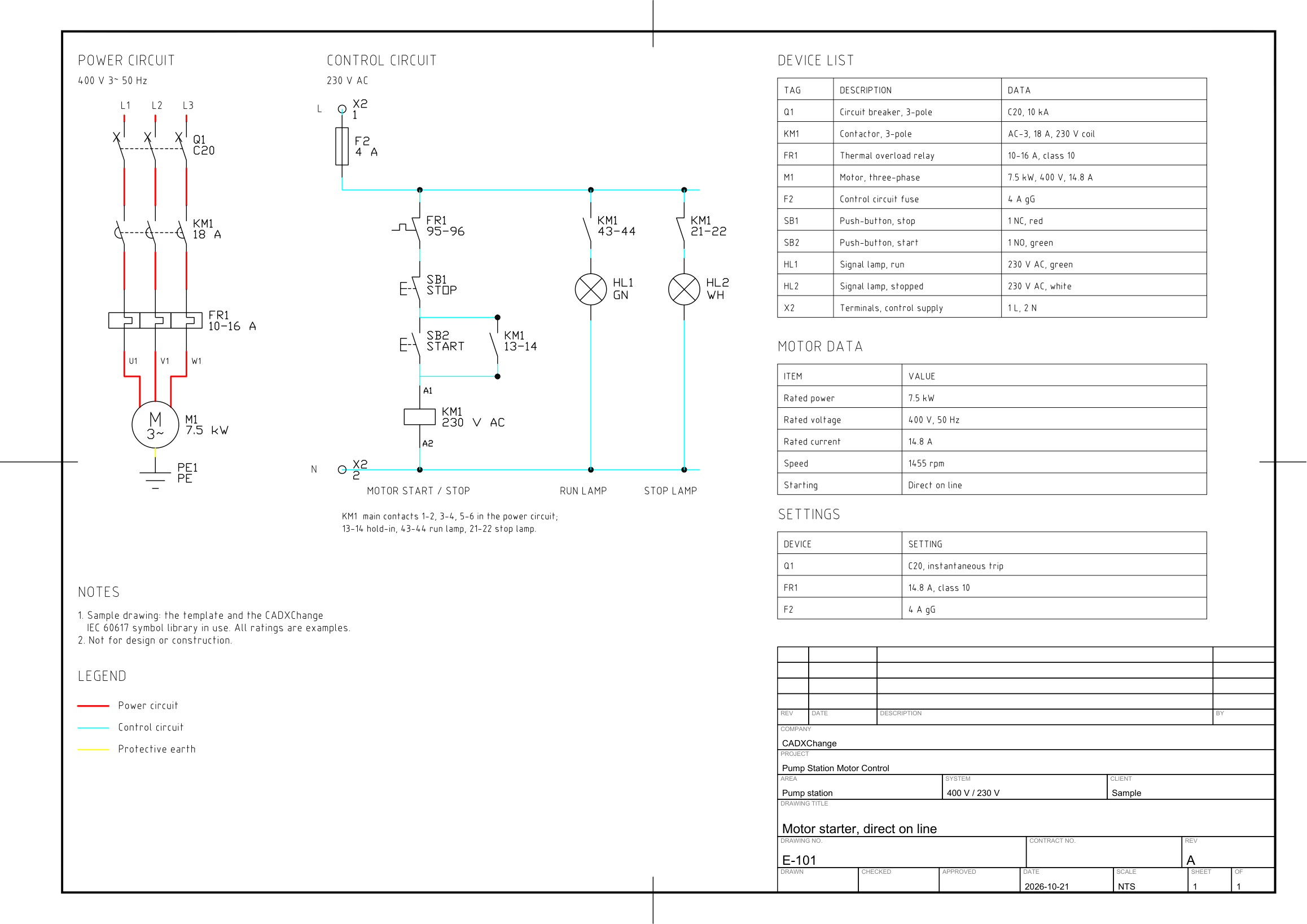 Direct on lineA 7.5 kW motor started across the line: circuit breaker, contactor and thermal overload relay in the power circuit; stop and start buttons with a hold-in contact, and run and stop lamps in the control circuit.
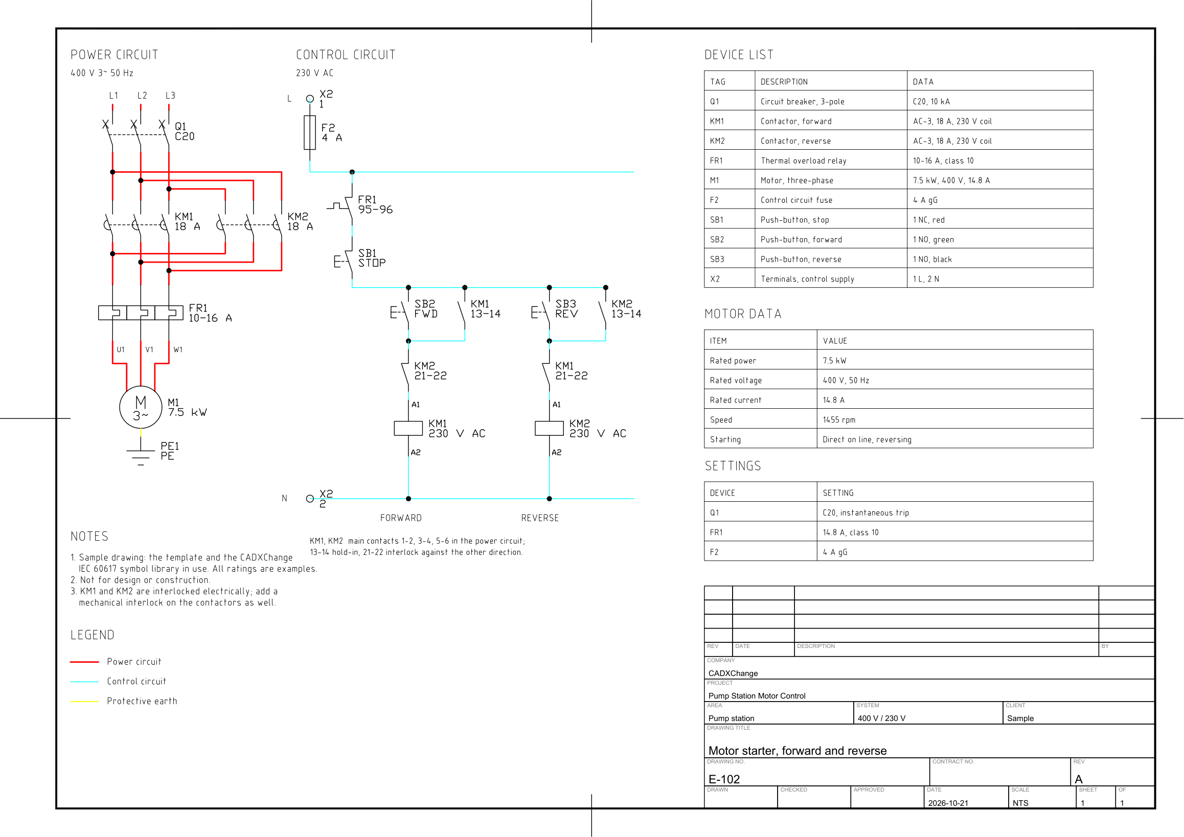 Forward and reverseA reversing starter for a 7.5 kW motor: two contactors that swap two phases, a shared stop button, separate forward and reverse buttons, and interlock contacts so that both contactors can never be on at once.
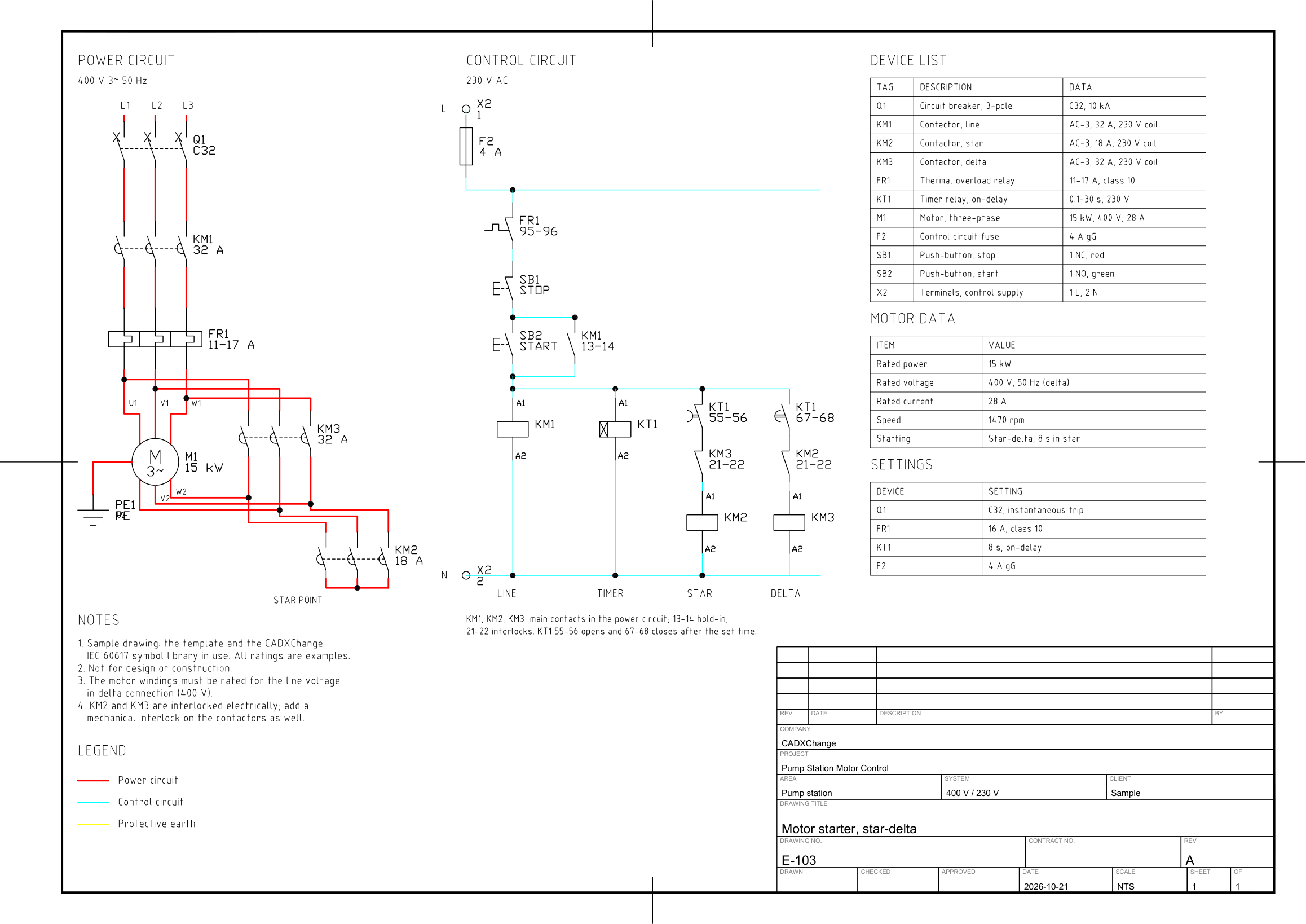 Star-deltaA star-delta starter for a 15 kW motor: line, star and delta contactors, a motor with six terminals, an on-delay timer that changes over from star to delta, and interlock contacts so that star and delta can never be on together.
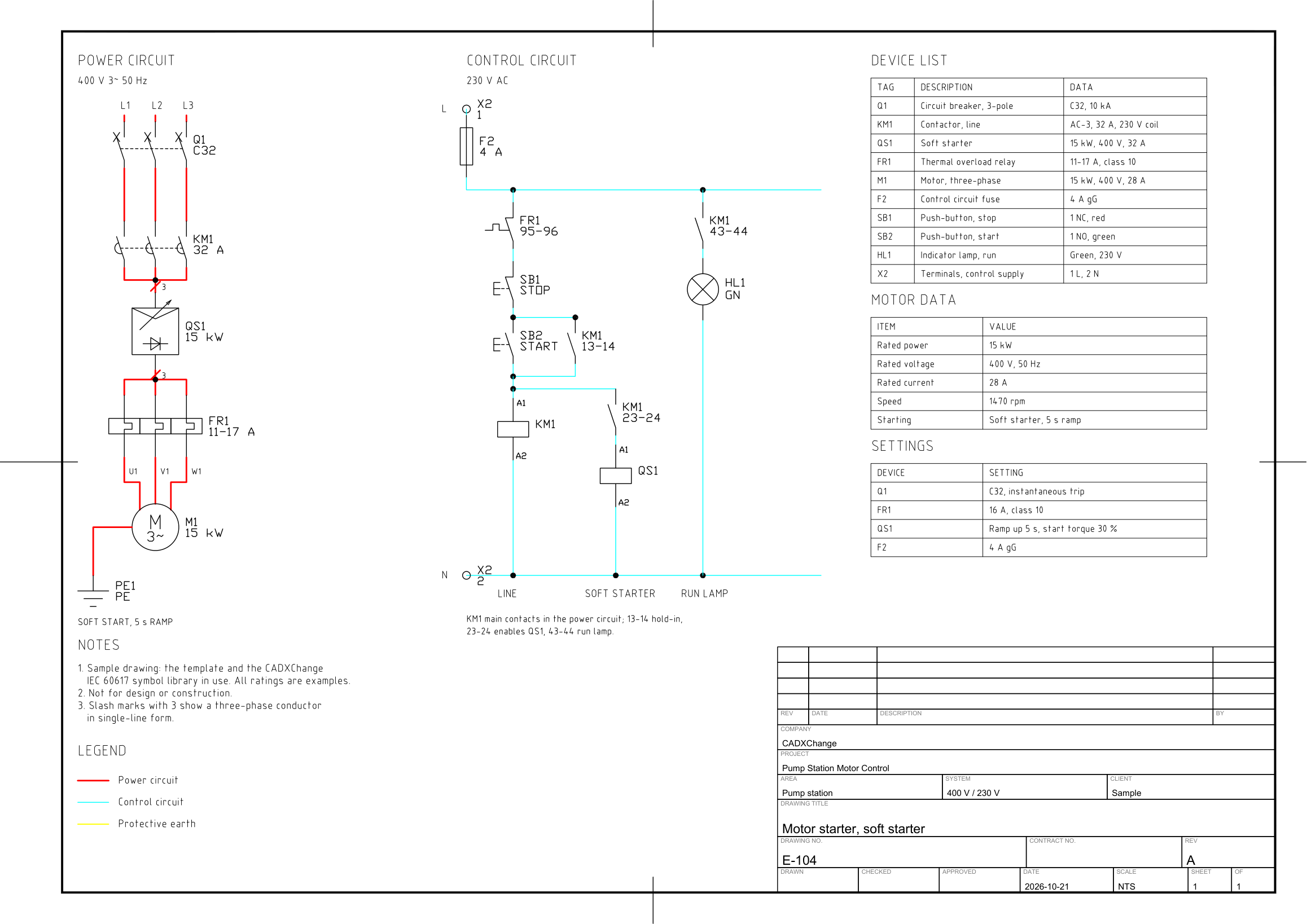 Soft starterA soft starter for a 15 kW motor: breaker, line contactor, the soft starter drawn in single-line form with three-phase marks, a thermal overload relay and the motor, with a control circuit where the line contactor enables the soft starter and lights the run lamp.
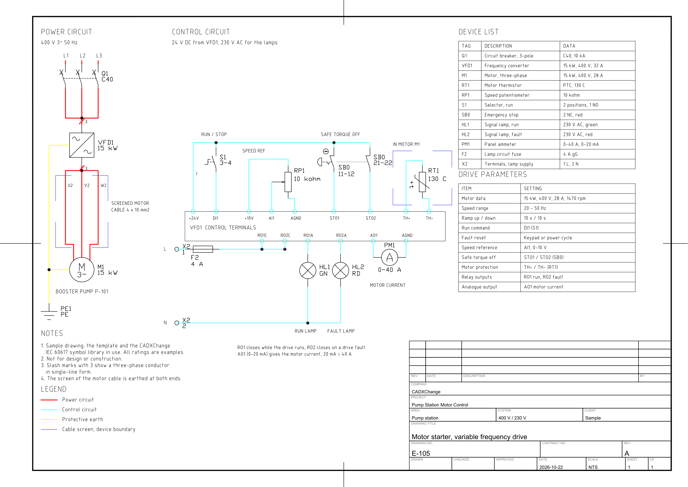 Variable frequency driveA 15 kW pump on a variable frequency drive: breaker, frequency converter, screened motor cable and motor, with the drive control terminals wired to a run switch, a speed potentiometer, a dual-channel emergency stop for safe torque off, the motor thermistor, two relay-output lamps and a panel ammeter.
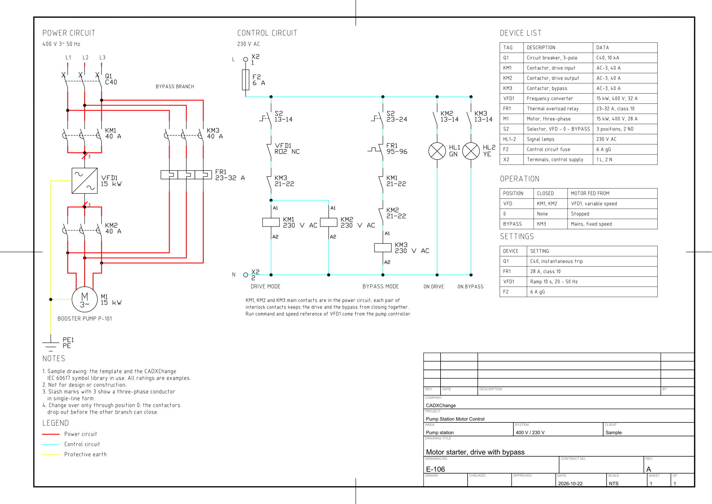 Drive with bypassA drive with a bypass: an input contactor, the converter and an output contactor on one branch, a bypass contactor with overload relay on the other, both feeding one 15 kW motor. A three-position selector, interlock contacts and the drive fault contact decide which branch runs.
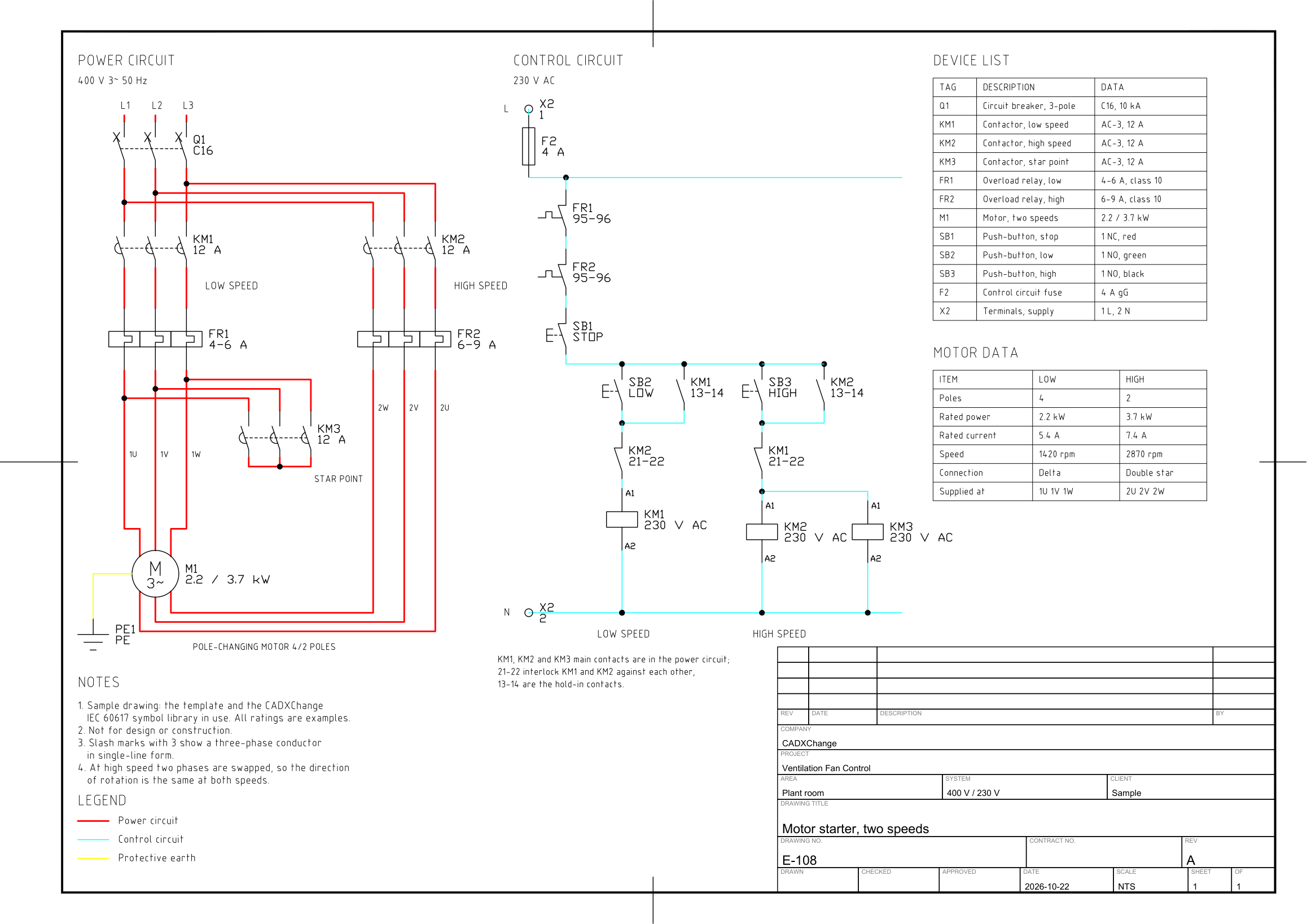 Two-speed motorA two-speed fan motor with a pole-changing winding: low-speed and high-speed contactors, each with its overload relay, a star-point contactor, the six motor terminals with two phases swapped at high speed, and a control circuit with a shared stop circuit, two start buttons and interlocks.